Laser Safety for Laser Operators

Pick up a book and drop it on the floor. As the book leaves your hand, it speeds up until, at the moment it hits the floor, it is traveling over 9 miles per hour. BANG! It hits the floor with a resounding crash as its energy of motion is converted into heat and noise energy. This energy of motion, as we all know, comes from gravity, the force that extends throughout space to hold the universe together.
But there is another, much more powerful, force which operates over much shorter distances. This is the electromagnetic force, which holds material objects together. It is very much stronger than gravity, which is why it is easy for the electromagnetic force that holds my hand (and the book) together to overcome the gravitational attraction on the book of the whole earth!
But this force can be made to extend far into space by moving the particles that it affects. If you spin a magnet, in a generator or magneto, you generate a powerful force that can charge your car battery, make a spark, or give you a painful shock. If you move electrons in a conductor such as a wire, you can drive a motor or light a light bulb. Because the movement of magnets or electric current produces this energy, it is called electromagnetic energy. Connect a source of electricity to the wire filament in a light bulb, and the electromagnetic energy produced is so powerful that you can actually see and feel it. The part that we can see is called light; the part we feel is called heat.
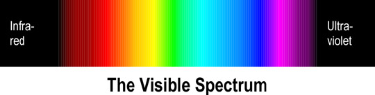
Electromagnetic energy radiates out from the source likes waves in a pond, which is why such waves are called electromagnetic waves. The distance between the crest of one wave and the one right behind it is called the wavelength. Light and heat are two forms of electromagnetic waves that differ only in their wavelength. Radio waves, TV transmissions, microwaves, x-rays and gamma rays are all examples of electromagnetic waves that differ fundamentally only in their wavelengths. Light has a wavelength of from 400 to 700 billionths of a meter; heat has a wavelength of from about one thousandth of a meter to a little less than one millionth of a meter. Radio, TV transmissions and radar have wavelengths of a few millimeters to over a kilometer or more.
Electromagnetic energy exists in nature in all wavelengths because the sun generates it. Most of this energy does not reach the surface of the earth because the atmosphere is opaque to it. But the atmosphere is relatively transparent to visible light, which is why living things have evolved receptors for light wavelengths. Sunshine consists of white light, a mixture of all the various wavelengths, or colors, to which the atmosphere is transparent. In addition, heat exists in harmful intensities in forest fires, which is why animals, which have the ability to run away, have evolved receptors for this radiation as well. Since excessive temperatures can be very harmful, heat receptors have the capability to produce an attention-getting and motivating response in animals known as pain.
Albert Einstein demonstrated that electromagnetic waves can be thought of as individual packets of energy called photons. The photon is the medium of transmission of electromagnetic energy from the source to the receptor. The energy of each photon is an inverse function of its wavelength. The shorter the wavelength, the higher the photon energy. Naturally, the waves are jumbled or chaotic, much like the waves formed if you throw a handful of pebbles into a pond. Visualized as photons, the individual photons are like people in a crowd running from an explosion; some go one way and some another, in different directions and with different energies. The movement is generally away from the source of the disturbance, but it is disordered. Electromagnetic waves of this type are called non-coherent.
Luminous objects, such as the sun, can be seen because the light that they emit impinges on the visual receptors on the eye. When all visible wavelengths are present in the same intensity, the light appears white. Differences in the amount of light observed at different wavelengths gives rise to the sensation of color. Light that consists of a single wavelength is said to be monochromatic, and the color observed is one of the spectral colors. Rainbows consist of a gradation of visible spectral colors from red to violet. Combinations of wavelengths in various proportions produce non-spectral colors. The ear interprets several simultaneous wavelengths of sound as separate notes, but, unlike the ear, the human visual apparatus cannot distinguish chords; it will interpret several reflected wavelengths as a single color. The colors brown and pink, for example, are blends of different wavelengths. In spite of the many browns and pinks in nature, there are no single wavelengths corresponding to these colors. That aspect of color that makes an object to appear to be one color rather than another is known as its hue. Hues are not defined for white, grays or black.
Objects that produce light, such as a light bulb, are colored according to the wavelengths that they produce in the visible spectrum. Since animals differ in the wavelengths to which they are sensitive, they perceive colors of light as hues different from those perceived by people. Where the visual spectrum is beyond that of humans, the animal will perceive hues that a human being cannot see at all, but even within the human species, what color something appears to be will depend upon differences between individuals, environmental factors, and even the individuals' emotional states. The condition of so-called color blindness causes the victim to perceive as the same hue wavelengths that most individuals would recognize as different hues. There are different kinds of color blindness, according to which hues the individual cannot distinguish.
When any kind of electromagnetic radiation strikes an object, it is reflected, transmitted, and absorbed, in various proportions, depending on the impinging wavelengths and the characteristics of the object. This is what allows non-luminous objects to be seen. Portions of the ambient light falling upon the object will be reflected into the eye of the observer. If the object reflects better at some wavelengths than at others, the object will appear to have the hue that is associated with the wavelength(s) most strongly reflected. A green object, for example, reflects green more strongly than other hues.
For each specific non-spectral color that is reflected by an object, there is a complementary spectral color that is absorbed. Complementary colors of spectral colors are either spectral or non-spectral. The complementary colors of the spectral colors of red, green and blue are, respectively, cyan, magenta and yellow.

Since what hue an object appears to be depends on the wavelengths perceived by the viewer, what hue an object actually is can be defined either with respect to the wavelength(s) reflected or the wavelength(s) absorbed. Pigments and dyes are substances that absorb certain colors and therefore cause the object to which they are applied to appear as the complementary hue. In addition, certain dyes have a property called fluorescence, by which they actually produce light, and therefore cause the object to take on the color that they produce.
Fluorescent dyes or other sources that produce light of various colors will make the object appear lighter when they are added because the eye receives more light. Combinations of red, green and blue lights produce white, so when red and green lights are combined, the resulting hue is yellow, which is the complementary color of the missing blue. Similarly, mixtures of red and blue lights produce magenta, which is the complementary color of the missing green, and mixtures of green and blue light produce cyan, which is the complementary of the missing red.
Because pigments absorb light, combinations of pigments will make an object appear darker than either one alone. The complementary colors of those that produce white light are cyan, magenta and yellow. Therefore, pigments that produce these hues (and that absorb, respectively, red, green and blue), can be mixed to produce the additive colors. This is why the inks in color printer cartridges are cyan, magenta and yellow. If cyan and magenta pigments or inks are mixed in equal proportions, they will absorb both red and green, producing a blue hue, the color of the light not absorbed by the mixture. Blue paint is therefore a 50/50 mixture of cyan and magenta. Similarly, equal mixtures of cyan and yellow inks will result in a green hue, which reflects only green, while equal mixtures of magenta and yellow will allow only red light to be reflected from the resulting red hue. Finally, if equal amounts of cyan, magenta and yellow pigments are mixed together, all the red, green and blue light falling on it will be absorbed, which makes the paint black. Color printers often have a separate cartridge of black ink because the ink manufacturer can produce a truer black mixture than the printer can, and the use of a separate ink for the most printing, which is black on white paper, conserves the expensive colored ink for color printing.
In addition to its characteristic hue, any individual color is also characterized by its saturation or chroma, which refers to the degree to which it is monochromatic, that is, to the degree to which it contains only a single wavelength. Monochromatic light has a saturation or chroma of 100%, and is said to be saturated. White light, which contains equal intensities of all wavelengths, has a saturation of zero. Colors with a saturation of less than 100% contain some white light and are therefore called unsaturated colors.
Finally, light of any given combination of hue and saturation can have a variable brightness (also called intensity, or value) which depends on the total amount of light energy present. When we say that something is bright or dark, we are referring to its intensity. Black has zero intensity; lighter grays have higher intensity, and what we perceive as absolute white has an intensity of 100%.

Animal eyes, including the human eye, are sensitive to non-coherent light in intensities found in nature, which illuminates objects of interest to them. For example, eagles and other raptors at their flying altitudes are able to see small prey animals on the ground that would be completely beyond the observational range of ground predators. Nocturnal predators are able to see in dim moonlight or starlight, whereas daytime hunters see best in sunlight. Insects are sensitive to ultraviolet light, which is invisible to humans, because ultraviolet light has better resolving power in the micro world in which the insects live. Climbing animals, which must judge distances accurately, have evolved stereoscopic vision for this purpose, while animals which must judge the ripeness of fruits and vegetables, such as man, are able to distinguish subtle differences in hue. Prey animals have eyes on both sides of their heads for all-around watchkeeping. Generally, terrestrial animals cannot tolerate light that is much brighter than bright sunshine, and are essentially blind in levels of light less intense than starlight. Plants, which need only to track the direction of the sun, have light receptors that fulfill this purpose. We see, then, that living things have evolved to use the light that exists in nature.
Lasers produce light that does not exist in nature. A stimulus, such as a chemical reaction, an electric current or intense light, is input into the laser and laser light comes out. However, the laser light is very much different from sunlight or starlight. Laser light is essentially 100% saturated, which means that it is all one very pure hue. Put another way, all the waves have the same wavelength, or all the photons have the same energy. The hue may be in the visible spectrum, in which case we can see it, or it may be of higher or lower wavelength, in which case we cannot. The heat receptors in our skin will alert us to impingement of laser radiation at heat wavelengths. If the heat radiation is sufficiently intense, it will register as pain. In addition, if invisible laser radiation is intense enough to cause rapid chemical changes in the skin, the pain receptors will alert us to the rate of damage in a last-ditch effort to protect us from a danger we cannot otherwise perceive.
Another characteristic unique to laser light is that is that it is coherent. This means that all the wavelengths are in step with each other, like perfect waves radiating outward from a stone thrown in a pond without a splash. Unlike the people in a panicked crowd, the photons are like soldiers marching in a parade, all going the same direction in synchrony with each other. Coherence makes laser light much more dangerous than non-coherent light of the same wavelength and intensity, as we shall see. For this reason,
As noted, the color of an object is due to the degree to which it absorbs and reflects incident radiation. Most surfaces have a certain roughness, which causes the reflected portion of incident light to be scattered, or reflected in different directions. This will cause the object as a whole to reflect essentially a composite of the incident light on it, so that it's hue will be the average of the hues of all incident light rays, modified further by the surface pigment. If the surface is extremely smooth, with irregularities approaching the wavelength of the incident light (400-700 nanometers), each ray of light will be reflected at an angle equal to the angle of incidence in a plain normal to the surface, and the surface will appear shiny. Such a surface is known as a specular surface. If the irregularities are smaller than the wavelength of the light, all the rays will be reflected in this way and the surface is called a mirror. If the mirror surface preferentially absorbs certain wavelengths, the reflected light will have the associated hue. Most mirrors today consist of aluminum or silver sputtered onto glass, which makes them almost perfect reflectors. Telescope mirrors often have the glass behind the reflecting surface to eliminate effects of the light passing through the glass. The glass is on the outside of commercial and residential mirrors to protect the reflecting surface on the back.
At this point we should note that a surface which is not specular at visible wavelengths may be specular at longer wavelengths. Brushed aluminum, for instance, appears dull in visible light, but it is almost a perfect mirror at infrared wavelengths. This is because the surface irregularities are larger than visible wavelengths, the longest of which is about 700 nanometers, but smaller than infrared wavelengths, which can be over a millimeter long.
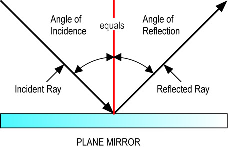
Perhaps the simplest optical instrument is the plane mirror, in which essentially all the light rays striking the mirror are reflected back from it at an angle that matches the angle of incidence. This produces the commonly observed effect of objects in front of the mirror appearing to be behind it. If the mirror is curved, the objects will appear to be distorted in proportion to the curvature of the mirror. The mirror can be curved deliberately to focus the light in the desired direction, including collecting it at a point. Because the reflecting quality of most popular mirrors is essentially independent of the wavelength (at least within the visible spectrum), the colors of reflected objects will appear to be unchanged and the position where an object appears to be will be independent of its hue.
If the radiation is transmitted through an object, the object will appear transparent, but not invisible. Most transparent materials transmit some wavelengths better than others, so objects seen through them will appear to be tinted with the hue of the favored wavelength, and the intensity of the transmitted light will be somewhat lower. But even a perfectly transparent object will not disappear. A clear pane of glass is a good example. In outer space, all wavelengths of light travel at the same speed, about 186,300 miles per second. This speed, often abbreviated "c," is the upper speed limit for any material object. Nothing can travel faster than light in free space.
When it is transmitted through a transparent object, however, light slows down slightly. The exact reduction is a function of the wavelength of the light and the material of which the object is composed. This effect is called refraction, and is measured by the index of refraction, or refractive index of the material at a specified wavelength. The refractive index is the ratio of the speed of light in free space divided by the speed within the material. For this reason, the refractive index of free space is exactly equal to 1.
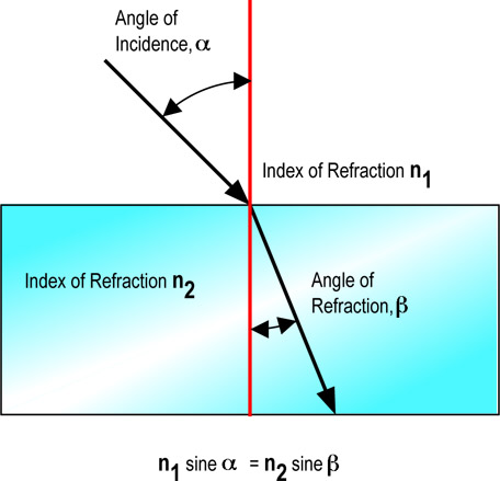
For yellow light, the refractive index of air is about 1.0002; water, 1.333; crown glass, 1.517; dense flint glass, 1.655; and diamond, 2.417. The practical effect of refraction is the bending of incident light, which is said to be refracted. A ray of light entering at an angle to the surface will be bent toward the normal so that the sine of the refracted angle (with respect to the normal to the surface) is equal to the sine of the incident angle divided by the refractive index. An entering ray will be bent toward the normal, an exiting ray will be bent away. Refraction is the cause of fish not being where they appear to be in water and for an object embedded in transparent plastic to appear to be in different places as viewed through the different faces.

Refraction can be used to bend light in a controlled manner. The simplest refracting instrument is the prism, in which light passing through it is bent at each surface. If the surfaces are parallel, the bending of light at one surface will be canceled by bending at the other, so an object observed through the prism will appear to be essentially in the same place that it actually is. If the faces are not parallel, the location of an object observed through the prism will appear to be displaced by an amount proportional to the angle between the faces. Continuous curvature of a refracting medium results in a lens, which distorts the image in a manner characteristic of the geometry of the surfaces through which the light passes. Lenses can be used to make an image appear to be larger or smaller or distorted in a specified manner, including displacement. They can also spread incoming light or focus it to a point or line. Lens surfaces can be cylindrical, spherical or (rarely) other shapes. In addition, the surfaces can be at angles with each other, which results in a prism effect being added to the lens. Perhaps the most popular lenses are those in eyeglass spectacles, the curvatures of which are specified in terms of the addition of spherical, cylindrical and prismatic curvatures. A single lens can also have different proportions of these curvatures specified at different places.
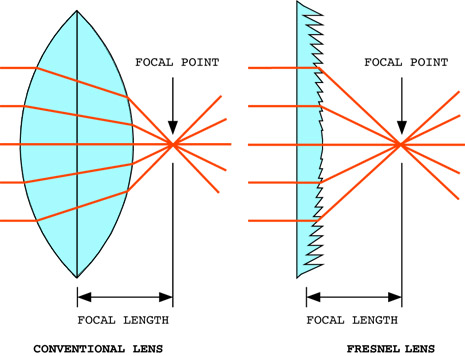
Since refraction takes place on the surface of a lens, marked curvature, which would make the lens excessively thick and heavy, can be duplicated in small increments on an otherwise flat surface, resulting in a Fresnel lens, named after its inventor. Augustin-Jean Fresnel. A Fresnel lens can be thought of as an aggregate of pieces of a thicker lens, with the thickness reduced to an average value across the lens. Fresnel lenses are commonly found in overhead projectors.
The index of refraction is dependent upon the wavelength, so for unsaturated colors the effect will be to spread the light into a characteristic spectrum. The separation of white light into the visible spectrum by a refracting glass prism was the method used by Sir Isaac Newton to demonstrate that colors do not consist of mixtures of white and black, as people believed previously. This effect is seen in the color fringes around objects seen through inexpensive optical devices (in which it is called chromatic aberration), the rainbow, the glittering colors of chandeliers and leaded glass doors and windows, and the fiery brilliance of diamonds, which are cut to enhance this effect.
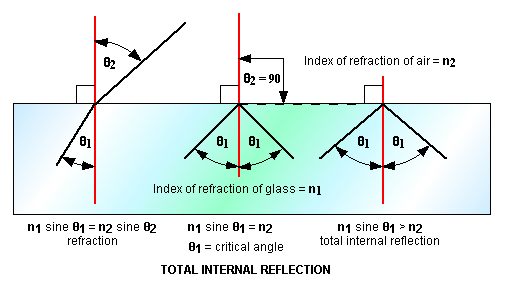
The cutting of diamonds to cause them to sparkle with different colors takes advantage of a phenomenon called total internal reflection. If a light ray inside a refractive material approaches the surface at or greater than the arc sine of the ratio of the outside refractive index to the inside one, the exit angle will be greater than or equal to 90 degrees. This means that the ray will be bent back into the material. The smallest angle at which this occurs is called the critical angle, and is different for different colors. Exit angles greater than the critical angle will result in the interface surface becoming essentially a perfect mirror, and the light ray will be reflected back into the material. In a diamond, multiple internal reflections take place, causing the different colors in incident light to appear to come from different directions within the diamond. If the light ray is introduced into a glass rod such that the exit angle is greater than the critical angle, the ray will be contained inside the rod. The tube can then be used as a light pipe, which will deliver almost all the light delivered into one end out of the other, even many miles away.
Light within the pipe will not escape out the side unless the pipe is bent into a radius that makes the incident angle less than the critical angle. This radius is therefore proportional to the diameter of the light pipe. Light pipes of very small diameter are therefore desirable, not only to reduce cost, but to make them flexible. Such light pipes can be made very thin, and are called optical fibers. Where the energy of the light is too large for a single optical fiber to carry it, several fibers can be put in parallel to preserve their individual flexibility. The assembly is called a fiber bundle or fiber optic cable.
To understand how a laser operates, one has to understand the basic structure of matter. The ancient Greeks, operating purely on logic, reasoned that, when any known substance is broken apart, the pieces are the same material as the original substance. But there must be a point, they concluded, when a substance cannot be divided further without changing it into something else. This smallest part of a substance they called "a tomos," meaning "not divisible." Our word "atom" is therefore of Greek origin.
The Greeks also noticed that a piece of amber, or petrified tree sap (the stuff they got the mosquitoes from in "Jurassic Park") would attract dust when rubbed vigorously. They suspected that rubbing the amber rubbed something off that caused it to attract the dust, but they didn't know what that something was. We now know that what is rubbed off is electrons. "Electron" is the Greek word for amber.
Early experimenters with electricity, including Benjamin Franklin, suspected that it consisted of particles. But they had no way of observing them directly until the invention of the vacuum pump. This made it possible to evacuate most of the air from sealed vessels. Such vessels are called vacuum tubes (even if the vacuum isn't perfect). Sir William Crookes used glass vacuum tubes to study electricity by passing an electric current through them. The current produced a glow very much like modern electric signs, which are long, skinny vacuum tubes. The glass allowed this glow inside the tube to be seen by the scientists outside. Researchers found that the glow was caused by charged particles, some of which were later identified as electrons. The electron has a negative electric charge and a mass that is almost negligible when compared to the atom with which it is associated.
Further experiments discovered that all material objects consist of atoms composed of a dense core, called the nucleus, surrounded by one or more spherical clouds or shells of electrons. Most of the atom is empty space, just like the solar system. The nucleus is like the sun and the electrons orbit around it somewhat like the planets.
In the solar system, the planets orbit in a plane around the sun. Unlike the planets, however, the electron paths form a cloud composed of spherical shells around the nucleus. The innermost shell has one or two electrons. The second shell has from one to eight electrons, the third has from one to eight, the fourth has one to eighteen, and so on. An electron can remain in any given shell only if all the lower shells are filled. Atoms with the same configuration in their outer shells tend to participate in chemical reactions in a similar manner. Chemical reactions between atoms involve the exchange or sharing of electrons in their outer shells. This exchange can take place between atoms of the same element or the atoms of different elements. Materials in which electrons are exchanged or shared between different elements are called compounds. All of the materials in nature are built up of elements and compounds.
Most elements and compounds can exist in three states; solid, liquid and gas. When a liquid condenses to a solid, it generally forms a crystal, in which the atoms are arranged in a regular three-dimensional array. The structure and characteristics of the crystal are determined by the arrangement of the electrons in the outer shells of the atoms of which it is composed. The energies that the electrons have are measured in electron volts, and are determined by the nature of the material. They are called permitted energy levels. An electron can have only these permitted energies, but not energies between the permitted levels. For this reason, the energy levels between permitted levels are called forbidden levels.
The energy band of the outer electrons is called the valence band because the valence of an atom is a measure of the way in which the outer electrons participate in chemical reactions. If the valence electrons in the outer shell are loosely bound to the parent atoms, the crystal will be a good conductor of heat and electricity. Many of the outer electrons will have enough energy to move from one atom to the next. Metals are good examples of this characteristic. The atoms in a metallic crystal can be thought of as being immersed in a "sea" of electrons, in which the electrons move freely among the atoms. The range of energies that these electrons have is called the conduction band because these electrons can contribute to the conduction of heat and electricity. At room temperature, the electrons in the valance band of good conductors are also in the conduction band.
In contrast, atoms of materials that are very poor conductors (and therefore good insulators) have electrons that are very tightly bound to their atoms. At room temperature, good insulators have virtually no electrons in the conduction band. The valance band and conduction band are separated by a large band gap of forbidden energy levels known as a forbidden band. Even under the influence of a very large voltage, very few electrons can be made to cross the forbidden band to the conduction band to conduct an electric current. Therefore, even when subjected to high voltage, the electric current through an insulator is extremely small.
Between the materials which are good conductors and those that are good insulators are the semiconductors. They are so called because the valance band and conduction band are very close together. The conduction band is close enough to the valance band that electrons can be moved from the valance band to the conduction band by an outside force, such as light, heat or electricity. Normally, most of the electrons are in the permitted levels of the valance band, and the material behaves as an insulator. At sufficiently high voltages, however, large numbers of electrons are moved to the conduction band, and the material becomes a good conductor. In effect, a semiconductor can be switched from an insulator to a conductor by the application of an external voltage or current. Transistors and integrated electronic circuits operate on this principle.
Absorbing a photon in a semiconductor can raise an electron from one permitted level to another. The electron will radiate a photon when it drops from a higher permitted level to a lower one. The energy that the photon will have, measured in electron volts, will be the difference between the two levels.
If an electric current is passed through a gas, some of the atoms will lose their electrons to the current flow. These atoms will subsequently capture other electrons. The captured electrons will radiate their excess energy, which will result in fluorescence at wavelengths determined by the change in energy levels. The associated colors of the radiation will therefore be characteristic of the composition of the gas and its pressure. In addition, the electrons participating in the current flow will impart random energies to the atoms of the conducting medium. This will cause it also to radiate energy at wavelengths that are a function of the temperature. Solids and liquids conducting an electric current also radiate in a temperature-dependent manner. The relative intensities of the electromagnetic radiation at different wavelengths define the color temperature of the conducting medium. Light from incandescent sources follows a color temperature sequence from infrared heat wavelengths through saturated red, saturated orange, unsaturated yellow to white and finally to unsaturated bluish white for an infinite temperature. Visible stars have these colors because their surfaces have the associated temperatures.
In addition to incandescent radiation, transparent materials can also emit light due to electron transitions between permitted energy levels. The trivalent chromium atom provides an example of this phenomenon in a crystal of aluminum oxide; this is the colorant that provides the red color of the ruby gemstone. In the dark, all the electrons will be in the lowest energy states they can occupy, which are collectively called the ground state. If the ruby is illuminated by white light, some of the outer electrons of the chromium atoms will be hit by incoming photons. Those that have sufficient energy to raise them to one of two levels; one at 2.2 electron volts, plus or minus a small increment due to thermal energy, and another at about 3.0 electron volts, will be absorbed. These energies correspond to green-yellow and violet light, respectively, so the ruby will absorb this light. The resulting light transmitted through the ruby consists of the white light minus the absorbed wavelengths, which results in a weak blue and strong red part of the spectrum. This makes the transparent ruby a deep red color with a slight purple tint.
The electron that has absorbed the photon now has excess energy. In this condition the electron is said to be excited. It can spontaneously return to the ground state through transitions to one of two permitted energy levels. One of the transitions will emit a photon in the infrared part of the spectrum, which will make the ruby slightly warmer. The second transition to the ground state will emit a photon of red light, which will make the ruby fluoresce in the red part of the spectrum. The red color of ruby is therefore due to absorption of green-yellow and violet light, and generation of red light.
An emerald results when beryllium and silicon are added to the crystal structure of a ruby. The beryllium and silicon modify the permitted energy levels so that the emerald absorbs red light, resulting in the green color of the emerald. However, the intermediate energy level is not changed, so that the emerald fluoresces with the same red color as that of the ruby. In ultraviolet light in an otherwise dark room, a green emerald will appear red.
The mechanisms of absorption and fluorescence are responsible for the operation of a laser. The ruby is a good example. When white light illuminates a ruby, some of the red light will be absorbed and will raise the electrons that absorb it into the associated excited energy state. These electrons will eventually spontaneously return to the ground state by the emission of a photon of red light. If the photon emitted interacts with another excited electron, that electron will immediately return to the ground state with the emission of a second photon of the same energy that it absorbed. It will also release the original incoming photon. In other words, the excited electron will be stimulated to release its energy by the emission of a second photon. This effect is called stimulated emission.
Under normal conditions, stimulated emission from a ruby will last only a fraction of a second, the time it takes for light to pass through the ruby and stimulate the emission of photons from excited electrons. The excited electrons will then return to the ground state after they have emitted these photons. Energy will also be lost by conductive heating and non-stimulated fluorescence. One can make this process continuous by continually supplying the ruby with energy of the same or shorter wavelengths, a process known as pumping. As the ruby is pumped, it will continue to emit light by stimulated emission and other mechanisms at wavelengths determined by its internal structure and temperature.
If two parallel mirrors are placed on either side of the ruby, the emitted light will be reflected back into the ruby, and will stimulate any excited electrons that remain to emit their excess energy and return to the ground state. In effect, the light exiting the ruby will be amplified by being passed multiple times through the ruby and stimulating other electrons to release photons. The ruby rod in this case is said to lase. If one of the mirrors is only partially silvered, it will allow some of the radiation to escape, thus losing energy. If the energy is replaced by pumping, the emission of radiation will increase until a steady state is reached in which the rate of energy loss by stimulated emission of radiation and other losses equals the rate of energy input by pumping. The light exiting the ruby through the partially silvered mirror will be monochromatic and coherent, the two characteristics of laser radiation. The term laser is an acronym for Light Amplification by Stimulated Emission of Radiation.
The earliest lasers were made of synthetic ruby in the form of thin rods. This geometry provides a large number of excited electrons in the long direction to be stimulated, and a short distance in the transverse direction for the light from the pumping source, usually a stroboscopic lamp in the form of a helix, to penetrate and excite the electrons. It also provides a large area to be exposed to the pumping light. Even today, pulsed ruby rod lasers are popular high-powered sources of monochromatic red light at 694.3 nanometers, which is the characteristic wavelength of ruby laser radiation.
In a semiconductor junction, such as those between the crystalline electrodes in a diode or transistor, there is an abrupt change across the junction in the energy levels associated with the valence and conduction bands. The flow of electrons across the junction provides a source of excited electrons that can return to the ground state and emit energy in the form of light. This light is nearly monochromatic but not coherent because the emission of each photon is due to a spontaneous transition of an electron to the ground state and not by stimulation by the absorption of a photon. A popular application of this principle is found in the light emitting diode, or LED, in which gallium with carefully controlled impurities is used as the emitting medium. The added impurities, called dopants, give the LED its characteristic colors of red, green, orange, and yellow by slightly altering the energy states that the excited electron can occupy. Recently, silicon carbide has been used as a dopant to produce blue LEDs. The combination of red, green and blue LEDs in single packages or in arrays makes it possible to add light colors to produce all visible hues in a single device or in a solid state display screen.
An LED can be constructed so that the junctions between the elements of the circuit are cut along crystal planes. This produces two very small partially transparent mirrors of excellent quality. In this case, some of the photons emitted at the junctions of the device will be reflected back into the emitting medium where they can stimulate electrons still in the excited state to emit radiation. In this case, the light emitting diode will produce coherent, monochromatic light. Such solid state laser diodes are popular sources of low power laser radiation because they are compact and inexpensive to manufacture.
Laser action is not restricted only to solid materials. A number of liquids and gasses can be made to lase if they are suitably pumped by an external energy source. The most convenient method of power input for liquids is usually intense light from a source around a tube in which the liquid is contained. This results in lasing activity similar to that in the ruby laser. For gasses, it is often convenient to supply the pumping energy by passing an electric current through the gas. Chemical reactions can also provide the pumping energy, so that a reaction in a gas container having opposing parallel mirrors can produce an intense pulse of laser light. Physical reactions, such as the rapid cooling of hot gas by expansion, can also provide this energy. Rapid cooling of carbon dioxide gas has produced lasers as powerful as 30 kilowatts!

Lasers have become valuable tools in medicine. They also have important uses in a number of other areas, as, for example, communications. Laser light can carry voice messages and digitally encoded information and can do so in large amounts because of its high frequency. Except in satellite-to-satellite communications, laser beams are transmitted via optical fibers. The speed with which the focal spot of a narrow laser beam can be controlled makes it suitable for a variety of applications in information processing--e.g., use in optical scanners, optical disc storage systems, and certain types of computer printers. Compact disk and CD-ROM readers use a solid state laser to read the information coded on this disk as a series of indentations on the surface. These indentations are cut on the master disk by a modulated laser beam.
The coherent nature of laser light allows it to be focused very precisely for measuring purposes. A laser beam can be projected onto a reflecting surface and reflected back to a sensor precisely to determine the distance to the reflector. Combined with a sensor array to provide a correcting signal to move the laser so that it is always pointing directly at the target provides a means to measure angular as well as linear motion. Such a system constitutes a very precise optical measurement device. The reflecting surface doesn't need to be very good; the actual surface of a part to be measured works quite well. If the laser is made to scan the reflecting surface, it can detect a depression or discontinuity in the surface and provide a correcting signal to follow such a discontinuity as it moves past the scanning beam. This system can be made to move a welding torch precisely to follow a previous weld bead or seam. It can also be used to guide an artillery shell or a bomb toward a laser-illuminated target.
Because the light from a laser is monochromatic, it can be used to illuminate a surface that is already very bright. A monochromatic filter that only lets the laser light through can filter out the unwanted illumination. The laser light can then be viewed directly or, if it is not within the visible spectrum, it can then be viewed by a suitable camera that provides an image on an appropriate display. For example, a laser illuminator can be used to observe a weld being made in real time. The welding arc light can be filtered out, leaving the laser as the only source of illumination. Using a high speed camera, such a laser illumination system can record the dynamics of an explosion or the burning process of rocket fuel, and play the recording back at a speed slow enough to observe the processes involved.
A highly intense laser beam can instantly vaporize the surface of a target. When laser pulses are concentrated on frozen deuterium-tritium pellets, they can heat them so hot that they initiate nuclear reactions. High-powered lasers can be used as space weapons to destroy reconnaissance and communications satellites and perhaps even ballistic missiles. These same capabilities have led to the use of lasers in research as well as in surgery. The laser microprobe is used for microanalysis of surface composition. Laser beams have been found to have a selective effect on cellular components, or organelles: those components that absorb light of the wavelength of the beam are destroyed, whereas transparent parts of the cells remain unaffected. Organelles such as mitochondria, which are responsible for cell respiration, or chloroplasts, which are involved in plant-cell photosynthesis, can be separately studied in this manner.
An intense beam of laser light can be used for small-scale cutting, scribing, and welding in certain industrial processes. Laser "pens" capable of producing such high-intensity light beams have proved useful in the assembly of various electronic components, such as computer memory and logic units consisting of integrated arrays of microcircuit elements. If laser energy can cut through a chip of silicon dioxide, it can certainly cut through your eyeball. For this reason...
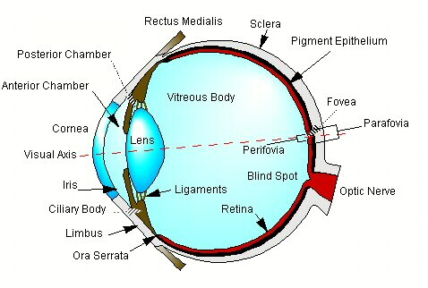
The human eye is a roughly spherical organ that maintains its shape because of internal pressure produced by a jelly called the vitreous body, about 95 percent of which is a clear fluid called the aqueous humor. This fluid provides nourishment to those transparent parts of the eye which do not contain blood vessels. The transparent front of the eye, which allows light to enter, is called the cornea. It is kept clean and moist by the lachrymal gland, which lies in the bony structure of the skull above the outer side of the eye. The cornea provides about 70% of the resolving power of the eye due to the difference in its index of refraction and that of the external medium, which is usually air. The index of refraction of the cornea is about the same as that of water, which is why the human eye cannot focus under water. The opaque part of the eye, sometimes called the white of the eye, is the sclera. It is attached at the limbus to the cornea by the ciliary body, which also connects to the four rectus muscles which cause the eye to rotate up and down and from side to side. The sclera, ciliary body and the cornea comprise the outer envelope, or globe, of the eye.
The eye also has an inner envelope, the uvea, with a hole in the front called the pupil, which allows light to enter the interior of the eye. A hole in the back, called the blind spot, is the location at which the bundle of nerves from the brain called the optic nerve exits the eye. Surrounding the pupil is the iris, a structure composed of sphincter and dilator muscles which control the amount of light entering the eye by adjusting the size of the pupil. The iris is the colored part of the eye, and divides the space between the cornea and the lens into an anterior chamber, in front of the iris, and a posterior chamber behind it. Surrounding the iris is the ciliary muscle that connects by ligaments to the crystalline lens. The lens provides about 30% of the resolving power of the eye, and is the part able to change focus. The ciliary muscle adjusts the shape of the lens to allow the eye to focus on near and distant objects. It is connected to the choroid, which forms the inner surface of the back of the eye, at a junction called the ora serrata.
The operation of the eye is fairly simple. Light entering through the cornea passes through the pupil and is focused by the cornea and lens onto an extension of the optic nerve called the retina, which covers the interior of the choroid up to the ora serrata. The size of the image formed on the retina is related to the size of the object being viewed in the same ratio as the focal length of the eye, 17 millimeters, to the distance of the object from it. For example, an object one inch in diameter at a distance of 17 inches will project an image 1 millimeter in diameter onto the retina.
The deepest layer of the retina is the pigment epithelium, which is a good absorber of visible light. On the surface of it is a layer of rods, which are sensitive relatively equally to all wavelengths of the visible spectrum, interspersed with cones, which discriminate color. The names of these cells is based on their relative shape, although they can both be shown to be composed of layers of folded membrane resembling a stack of pancakes. Above the layer of rods and cones is the connecting network of bipolar cells, which receive information from the rods and cones and transmit it to the layer above that, the ganglion cells. These carry information out of the eye through the optic nerve to the brain. The light that has passed through the layers of nerve cells, which are only partially transparent, stimulates the rods and cones. These, in turn, produce the impulses that stimulate the nerves to create an impression of the visual field that is sent to the brain.
The most sensitive portion of the retina is the fovea centralis, or fovea, which has a much higher density of cones than anywhere else on the retina. These cones are exceptionally thin, and are so densely packed that there is no room for rods. The superstructure of nerve cells is also very thin over the fovea, which results in the formation of a depression, or foveal pit, so that the cones in this area are able not only to discriminate smaller changes in light intensity, but also to operate at lower light intensities. This makes the region of the fovea a good receptor of visual information, including color. The feedback process that operates the rectus and ciliary muscles will automatically move the eyeball and focus the lens so that the image of an object of interest is projected directly onto the fovea. If the image is so large that its image covers more or the retina than the fovea, the eye will move in a rapid scanning movement, called saccadic movement, to project all portions of the image successively onto the fovea.
Surrounding the fovea is the perifovea, a ring of densely packed rods interspersed with a less dense matrix of cones. Because rods convey the sensation of intensity or brightness, whereas cones convey color information, this arrangement produces a receptor mechanism that tells the brain how to move the eye to bring images at the edge of the fovea into focus on the fovea. A ring of less densely packed rods and cones, called the parafovea, surrounds the perifovia. The concentric arrangement of the fovea, perifovia and parafovea, along with the integrating software in the brain, constitutes a system by which the entire field of view is analyzed for images of interest. Feedback is provided to the rectus muscles to being them into alignment on the fovea and to the ciliary muscles to adjust the lens to bring them into focus. It also provides a backup mechanism to allow images that cannot be resolved by the fovea in dim light to be seen by looking to the side of the object to project it onto the perifovea.
In effect, this provides two separate but interrelated imaging systems, one of narrow view that resolves color, and one of wider view that provides a monochrome image. In humans, this allows the person to concentrate on objects of interest while simultaneously watching for danger. Since the perafovea is primarily sensitive to movement in the visual field, it is particularly good at watching for predators. This partially compensates for the reduction of the field of view that results from location of both eyes on the front of the face, which is necessary for stereoscopic vision.
Although the process by which an image is formed on the retina is simple, the process by which the brain recognizes the image as being representative of an external object is extremely complex, and not completely understood. For every nerve fiber which goes to the brain, there are about 150 receptors in the retina, so there is some mechanism which goes on in the eye itself which selects the visual stimuli that will be transmitted as messages to the brain. The average distance between cones in the fovea is about 1.75 micrometers, which suggests that the smallest image that could be resolved would be one that impinges on one cone but not those surrounding it, that is, a circle of a diameter of 3.5 micrometers. Considering that this single cone would have a chance of 1 in 150 of being connected to the brain, a single image would have to stimulate about 103 receptors, for a total area of 137 square micrometers (or a circle of a diameter of 13 micrometers), to have a 50/50 chance of being recognized. However, studies have shown that a normal human being can reliably recognize images as close together as 0.4 micrometers as being of two separate objects, and can recognize a single image having a diameter of 7 micrometers. At a viewing distance of 18 inches, this corresponds to an object diameter of 7.4 thousandths of an inch (0.0074 inches) which, not incidentally, is only slightly smaller than a single pixel on a VGA computer display.
The process of seeing is automatic in sighted people, but it is a process that must be learned. People blind from birth whose sight is suddenly restored often report great difficulty in learning to interpret the sensation of sight as having something to do with the world around them. Well-established optical illusions demonstrate that emotional states and other physical and chemical factors that affect the brain profoundly influence the sensations of color, continuity, shape, size, movement, and the ability to see at all.
There are many mechanisms that protect the eye from damage. Chief among these is the orbit, the circle of bone in the skull that surrounds the eye. This provides a bumper that protects the eye from blunt trauma. In addition, the eye is held in place in the orbit by surrounding fatty tissue, which cushions it against shock. The lachrymal glands provide fluid for tears. They continuously bathe and clean the surface of the eye, and provide necessary nutrients and lubricants, while the eyebrows and eyelashes provide a filter from airborne dust, dirt and rain.
The blink reflex is an involuntary mechanism by which excessively bright light, trauma, or irritation to the eye results in the automatic closing of the eyelids to provide a protective cover. The time from the reception of the stimulus to the closing of the eye is on the order of a quarter second. The iris opens to its maximum diameter of 7 millimeters only rarely; most of the time the diameter is from 1 to 4 millimeters, which limits light input to the eye and improves focus. In addition, muscles around the eyelids provide for a further reduction in light input by squinting. The eye is designed to function in a range of intensities between bright sunshine and starlit night, and is not generally harmed by normal daily exposure to visible light intensities in this range.
The human eye is a very effective imaging system, but it is not perfect. Also, in addition to inherent imperfections in the healthy visual mechanism, age, trauma and other factors impair its functioning to the point where most people have a noticeable deterioration of their sight by middle age.
The most obvious imperfection in the eye is in the lens. Like other single lens systems, the human lens suffers from chromatic aberration, which results from the different indices of refraction of the lens for different wavelengths of visible light. This causes images viewed in unsaturated light to be projected onto the retina with colored fringes, or halos. The different wavelengths of light are focused at different distances from the lens, so that only a single wavelength is actually in focus on the retina at any one time. Normally, the brain edits out these distortions so that colored objects appear to be in sharp focus when we are looking at them. This lack of ability to focus white light provides a protective mechanism in which only a portion of the energy of bright daylight is focused on the retina, thus limiting the power input to it.
A further protective mechanism is provided by the fact that the lens does not focus even a single wavelength accurately. For small pupil openings, that is, 2 millimeters or so, the focus is fairly sharp, as required for daytime hunting, climbing and food gathering. But for the largest pupil diameter of 7 millimeters, which occur only in very low light intensities, the image on the retina is slightly blurred. The result of this condition is that more rods and cones are involved in resolving images at low light levels, making it possible to see more things (although less clearly) than would be possible if the lens were perfect.
Another condition, sometimes called floaters, is caused by cellular debris in the interior of the eye. These appear as black or gray spots that move with the eye but tend to lag somewhat behind eye movement. Virtually everyone has them at one time or another, and they become more common due to normal cellular deterioration with advancing age. These spots are generally edited out of the visual field by the brain, so that they are often not noticeable unless one is looking at a fairly smooth, featureless surface, such as the daytime sky or a sheet of blank paper. There does not appear to be any benefit associated with this condition, and there is no simple cure.
The most common visual defect is refractive error, in which the lens does not focus images properly on the retina. The lens may be too thick or too thin, or it may be distorted in some other way. Refractive error can be corrected by spectacles or contact lenses that, together with the imaging apparatus of the eye, form a series of lenses that focus images properly. If the distortion of the lens is not too severe, the correction can be made by shaping the cornea as necessary. This can be done by conventional surgery, as in radial karatotomy, or by laser surgery that sculpts the eye by vaporizing unwanted tissue, a process called laser in-situ keratomileusis or LASIK.
As the healthy lens ages, it loses its elasticity, so that middle-aged persons have difficulty focusing on near objects. This condition is called presbyopia. In effect, the person requires one set of spectacles for seeing near objects, and (sometimes) another for seeing far objects. Generally, two actual sets of lens shapes are needed, but the common approach is to put the two corrective lens shapes together on a single piece of glass or plastic, one for each eye, called bifocals. Sometimes the outline of the secondary lenses can be clearly distinguished, but more modern practice is to blend the smaller lens into the larger in a gradual transition so that the outline of the smaller lens disappears. Very elderly people may require three or more different lens shapes, in which cases their spectacles are called trifocals or multifocals.
Heat, ionizing radiation, infection, metabolic disorders or hereditary factors complicated by advanced age can cause the lens to become opaque, a condition known as cataract. The entire lens can be affected, or only the periphery (peripheral cataract) or a few spots (punctate cataract). Cataracts from various causes are the chief cause of blindness throughout the world. Correction of this disorder involves surgical removal of the lens and the use of spectacles, contact lenses, or, more commonly, artificial implanted replacement lenses called intra ocular lenses, or IOL's. Trauma or infection of the cornea can cause a similar loss of sight due to the formation of scar tissue over the cornea. In this case, the cornea is no longer transparent and must be replaced.
Another condition aggravated by age is glaucoma, a rise of pressure of the aqueous humor in the interior of the eye. It is caused by injury to the mechanism that drains the aqueous humor. The increased pressure inhibits the flow of blood to the retina, resulting in atrophy of the portions of the retina and overlying structure deprived of adequate blood supply. Treatment for glaucoma includes surgical reconstruction of the drainage structures and the use of drugs to control the production of aqueous humor, although any loss of sight caused by damage to the retina is permanent. Macular degeneration is another disorder in which age-related loss of circulation leads to degeneration of the retina with progressive permanent loss of sight. Early stages of the disease are treated by drugs or changes of lifestyle which improve circulation generally, and by the use of magnifying spectacles to produce larger images on the retina.
A more serious condition is a scotoma, or blind spot, caused by damage to the retina. Normally, the human visual field has a blind spot outside the parafovea where the nerves from the retina exit the uvea through the bundle of nerve fibers of the optic nerve. The brain normally edits out this spot so that it is not noticeable in normal vision. However, any damage to the rods and cones in the fovea will result in a blind spot in the visual field. Such damage is usually permanent.
This is what makes laser light so dangerous; that it defeats the protective devices of the eye and causes permanent damage by a variety of means. That is why you should...
First of all, there is no practical limit to the intensity of laser emission. It is relatively easy to construct a laser that is a million times brighter than the sun. Therefore, the eye can be exposed to overwhelming intensity from even low power lasers before the blink reflex is able to protect it. A 100-watt incandescent light is painful to stare at from distances of less than a few feet but, because it approximates raw sunlight, it triggers automatic responses such as blinking, squinting, tearing and turning of the head, all of which protect the eye. These involuntary reactions are called the aversion reflex. A 100-watt visible laser, on the other hand, can literally blast a hole in the retina; by the time it takes to blink, the damage is already done.
The reason for this is that the potential for harm is determined by the power density or irradiance in watts per square centimeter. At a distance of a yard, the retinal irradiance of a 100 watt bulb is about .0001 watt per square centimeter. This is about the limit of deliberately tolerable visible irradiance, and is the maximum permissible exposure (MPE) for visible radiation for short exposures. A 100 watt laser, can produce irradiances of 250 watts per square centimeter or more, two and one-half million times the MPE. In most cases, the concern is with the total energy delivered to the eye, that is, the integrated irradiance over time. This parameter is called the radiant exposure, and is measured in joules (watt-seconds) per square centimeter. The MKS unit, joules per square meter, is rarely used in describing ocular hazards.
The concept of MPE requires a little more explanation. This term is used by the American National Standards Institute and defined in ANSI 136.1, 1993 as: "The level of laser radiation to which a person may be exposed without hazardous effect or adverse biological changes in the eye or skin." It may be considered synonymous with the American Conference of Government Industrial Hygienists (ACGIH) threshold limit value (TLV), the WHO exposure limits, and the US Army protection standards. The MPE is arrived at by a variety of different methods and studies, and in some cases is interpolated or extrapolated from limited data. Perhaps the ACGIH says it best in its preamble: "The threshold limit values are for exposure to laser radiation under conditions to which nearly all works may be exposed without adverse effects. The values should be used as guides in the control of exposures and should not be regarded as fine lines between safe and dangerous levels. They are based on the best available information from experimental studies." For this reason, ANSI supports the position that in an industrial organization, the laser safety officer (LSO) can reclassify laser systems or establish different limits based on unique circumstances.
Because laser light is monochromatic, it defeats the defensive mechanism that results from chromatic aberration. The natural tendency of the eye to focus on images in the visual field virtually guarantees that all the visual input from a laser that reaches the lens will be focused exactly on the fovea. This ability to focus is further enhanced by the coherence of laser radiation. The energy from even a low power laser can be focused to an extremely small spot, with a power density hundreds of times more than that necessary to burn a hole in the retina within the visual field of the fovea.
The energy of the laser can have a catastrophic effect on areas of the eye other than the fovea. Scotomas off the visual axis are generally less dangerous than directly on the fovea because the brain tends, over time, to edit off-axis blind spots out of the visual image. However, damage to a blood vessel can cause rupture and subsequent bleeding into the interior of the eye. This will make it impossible for that eye to see through the pool of blood within it. Although the natural drainage of the eye will eventually get drain most of the blood, some blood clots and other debris may remain within the visual field forever.
The irradiance of even invisible laser radiation can easily be so high that it cooks the lens or chars the cornea. These types of damage are often permanent, and can only be alleviated by replacement of the damaged parts from organ donors. Of course, such high densities are also dangerous to the skin as well; a five-watt infrared laser, the emission of which is invisible, can cut right through exposed skin and the muscle underneath it, right down to the bone. Pulsed lasers can deliver enough energy in one pulse to cause exposed skin at the target literally to explode!
Lasers are divided into four classes according to their potential to cause injury. They are:
Class 1 - Essentially non-hazardous
Class 2* - Hazardous to the eye, but natural reflexes (e.g. blinking) provide protection
Class 3** - So hazardous to the eye that natural reflexes do not provide sufficient protection, but diffuse reflections is not hazardous. Not hazardous to exposed skin.
Class 4 - More hazardous than the others.
*Class 2 is sometimes divided into class 2a (where the laser radiation is not intended to be viewed) and class 2b (otherwise).
**Class 3 is sometimes divided into class 3a (used in a situation not normally hazardous) and class 3b (otherwise).
Rationale for classification can perhaps best be demonstrated by considering visible lasers.
The development of good optical telescopes in the 19th century allowed astronomers to reach the practical limit of resolving power of individual stars seen through the earth's atmosphere. Stars are point sources of light, having no discernible diameter. When highly magnified, individual stars appear to be rings of light and dark surrounding a bright fuzzy spot in the center. A British astronomer, Sir George Airy, showed that this image was due to the wavelike nature of light, and was a fundamental limit of optical systems operating in the visible spectrum. The distinctive pattern formed by a point source is referred to as an Airy disk, and a point source that is resolved to an Airy disk is said to be diffraction limited. The diameter of an Airy disk is taken as the diameter of the first dark ring around the fuzzy spot.
The resolving power of the fovea is diffraction limited in that the smallest spot that can be resolved is the Airy disk of a point source. This limitation occurs with a pupil diameter of about 2.2 millimeters, which provides the sharpest focus. Pupil diameters larger than this result in poorer focus because of the tendency of the lens to blur the images for larger iris openings. The Airy disk diameter of the smallest resolvable image on the fovea is about 7 micrometers, as previously noted. The ratio of the area of a circle of 2.2 millimeters diameter (the pupil) to that of one 7 micrometers in diameter (the spot on the fovea) is about 100,000. This is the effective amplification factor of the eye with a 2.2 millimeter pupil and a diffraction limited point source. Note that the amplification factor depends upon pupil diameter. This means that power density (power per unit area) input through the pupil (at the cornea) is amplified 100,000 times where it hits the retina. Of course, an intensely bright spot would immediately trigger the blink reflex, which would interpose the eyelids between the laser and the cornea, shutting off the source of power into the pupil within 250 milliseconds. With this spot size and time limitation, the retina can safely withstand an input of 250 microjoules of visible wavelength energy.
This much energy will be supplied in 250 milliseconds by a 1 milliwatt source. Therefore, we need to limit the power input to the pupil to 1 milliwatt. If we don't know what the potential is for intercepting the laser radiation at the cornea, we can conservatively assume that all of the laser power will enter the pupil and limit the total laser power to 1 milliwatt. This is the dividing line between a class 2 and a class 3 laser.
We may also note that 250 microjoules over a spot size of a diameter of 7 micrometers is a power density of 650 joules per square centimeter. Based on the amplification factor of 100,000, we would expect that the MPE at the entrance of the pupil would be 650/100,000 = 6.5 x 10⁻³ joules/square centimeter. The actual MPE for intrabeam ocular exposure to a visible laser for a time period of 1.8 x 10⁻⁵ to 10 seconds turns out to be 1.8 t0.75 x 10-3 joules/square centimeter, which, for 250 milliseconds, is 0.636 x 10⁻³ joules/square centimeter. Although this seems like a value ten times smaller than that calculated above, it is based on a 7 millimeter pupil diameter. The actual power delivered to the retina with a pupil diameter of 7 millimeters would therefore be 0.636 x 10⁻³ joules/square centimeter x p x (0.7/2)2 square centimeters = 245 microjoules at the spot on the retina. Pretty close! (The MPE of 0.636 x 10⁻³ joules/square centimeter may also be found in Figure 4, ANSI Z136.1, 1993, but it may be hard to read.)
Since the power limit is based on the aversion reflex, which doesn't work if you can't see the radiation, class 2 applies to only visible lasers. Note that this does not mean that the direct radiation from a class 2 or diffuse reflection of a class 3 laser won't hurt you; what it means is that natural reactions will save you from the radiation if you happen accidentally to glance at it. If you intentionally stare at it, you may cook your fovea. Hence the rule:
Of course, it is possible that the image will not be bright enough to trigger an aversion reflex. In this case, the laser power must be limited to what the eye can withstand continuously. A safe limit would be that equivalent to average outdoor daylight, which has a power density of about 13 microwatts per square centimeter. Under such conditions the pupil contracts to a diameter of about 2 millimeters, which provides a pupil area of 0.031416 square centimeters. The power actually delivered to the pupil would thus be power density times pupil area, which in this case would be 0.4 microwatts. This is the dividing line between class 1 and class 2 visible lasers.
Unfortunately, it's not quite that simple. Because daylight consists of the entire spectrum, correction factors must be applied for monochromatic light, which is somewhat less hazardous at lower energies (wavelengths longer than 0.550 micrometers). The correction factor is 10 to the power of 15 times the difference between the actual wavelength of the laser, in micrometers, and 0.550. Therefore the equation for the power limit P of a class 1 visible laser is:
P = 0.4 x CB x 10-6 watts, where CB = 1015 x (l - 0.550) for l longer than 0.550 micrometers, CB = 1 otherwise.
For ultraviolet lasers, analysis is a little more complex. Retinal damage is not a concern, since the lens, aqueous humor and cornea absorb UV, which therefore never gets to the retina. The problem is that the human lens grows throughout the individual's lifetime, with cells present at any given time being compressed in the center as new cells are added on the outside. Damage to these cells that is not evident immediately can lead to cataract over time. Corneal damage is more painful, since there are pain receptors in the cornea, but less hazardous since the cornea heals rather quickly. The painful acute injury known as snow blindness or welders' flash is caused by UV injury to the cornea, but those affected usually completely recover. Because UV is invisible, class 2 does not apply to it. The transition point between class 1 (non-hazardous) to class 3 (hazardous) is from 9.6 nanowatts (!) for short wavelengths (UV-C) to 3.2 milliwatts for long wavelengths (UV-A). The short wavelength radiation is sometimes called actinic, and is especially hazardous to the cornea.
Infrared lasers present a similar hazard. Absorption mechanisms differ at different wavelengths so that for near infrared (IR-A), the hazard is primarily to the retina, while the hazard for far infrared (IR-C) is primarily to the lens because of the potential for cataract. In fact, cataract is a common chronic industrial injury in glassmaking and steelmaking industries, both of which involve exposure to high intensities of infrared radiation. The dividing points for IR-A between class 1 and class 3 for a workday exposure are 128 microwatts at 0.7 micrometers up to 95 milliwatts 1 millimeter in several steps. Wavelengths above one millimeter are considered radio frequency radiation, such as that in a microwave oven. There are established safety limits for such radiation based on the excitation of water molecules in the body.
Rather involved calculation indicates that, for a diffuse surface, the reflected power impinging upon the eye is safe up to an incident power input of about 500 milliwatts or 1/2 watt. This is the dividing line between class 3 and class 4 for all lasers. If the surface is shiny, there is a possibility that reflected energy would be greater than calculations for diffuse surfaces would indicate. Therefore, where there is a possibility that the laser beam could be reflected from a shiny (specular) surface, the limiting values for direct exposure should be used for hazard calculations.
Actually, one does not have to be concerned about the classification of lasers, except to know which ones are hazardous. Manufacturers of lasers are required to specify on the laser what the class is based on worst-case analysis. This classification is based on the entire device, or system, which contains the laser, not the laser itself. For example, a class 2 laser system could contain a class 4 laser with a window that limited all of the radiation to that which produces an aversion response to preclude injury. Sometimes such a system is sometimes called a laser product. A class 3 laser product should be treated as a class 3 laser for the purposes of analysis.
An area where personnel could be exposed to hazardous laser radiation must be controlled to preclude accidental exposure. The American National Standards Institute has established a uniform format for signs warning of laser radiation. They must be posted "conspicuously" around a controlled area to warn personnel of the hazards associated with class 2, 3 and 4 lasers. There are five essential elements for these signs.
Laser Symbol: The laser hazard symbol is a sunburst pattern consisting of two sets of radial spokes of different lengths and one long spoke, called a tail, radiating from a common center, like this:

Signal words: Where the potential for exposure to radiation is less than the MPE, the word CAUTION must be used. The CAUTION sign is yellow with a black rectangle behind the word CAUTION in yellow block letters on top, and a red or black laser radiation symbol below. The word NOTICE is substituted outside an area containing a temporary hazard, such as during periods of service or test. In such cases, the appropriate CAUTION or DANGER sign is still used to define the controlled area. Where the hazard is potential for exposure to radiation in excess of the MPE, the word DANGER is used. The DANGER sign is white with a black rectangle at the top. Superimposed on the black rectangle is a red ellipse with a white border. Within the ellipse is the word DANGER in white block letters. The laser symbol is red.
Hazard definition: The words LASER RADIATION appear above the tail of the laser symbol. The word LIGHT can be substituted for RADIATION for visible lasers. For all others, the word INVISIBLE appears before the word LASER.
Precautionary instructions: The notice above the laser symbol tail also includes what precaution to take. For class 2 and 3a lasers, the instruction is "Do Not Stare Into Beam or View with Optical Instruments." For all other class 3 lasers, "Avoid Direct Eye Exposure." or "Avoid Direct Exposure to Beam" as appropriate. For class 4, "Avoid Eye or Skin Exposure to Direct or Scattered Radiation." Additional instructions may be included, such as "Knock before Entering," "Do Not Enter when Light is On," "Restricted Area," and so on.
Specifications: Information about the laser such as type, wavelength, pulse width, power output, energy per pulse, and so on is placed below the tail of the laser symbol, followed by the classification of the laser. If class applies to the system (possibly containing a higher class laser within it), the classification is that of the system.
Of course, the whole purpose of the signs is to alert people to the laser hazard, so that they...
When analyzing an apparatus containing a laser, one can assume that a class 1 or class 2 system will be safe for situations in which people do not look intentionally into the beam or use optical instruments that concentrate the radiation. For classes above class 2, or where intentional observation or use of optical instruments is reasonably anticipated, one must determine the nominal hazard zone (NHZ), in which exposure to laser radiation more intense than the MPE is reasonably probable. Within the NHZ, wearing of protective equipment (e. g. laser goggles) is usually necessary.
A hazard analysis must also consider the exposure time. Specified values of the MPE are calculated for durations up to 3 x 10⁴ seconds (8.33 hours), which is considered the limit of daily industrial exposure. The MPE for aversion response limited exposures is usually the aversion response time (250 milliseconds), or the pulse duration for single pulsed lasers, whichever is shorter.
For most analyses, the hazard is based on the radiant exposure, the amount of energy that is deposited by the laser beam at the vulnerable site divided by the area of that site, that is, in joules per square centimeter. The areas of the vulnerable sites incorporated into the limiting apertures specified in Table 8, ANSI Z136.1, 1993, as follows:
| Summary of Table 8, ANSI Z136.1, 1993 Limiting Apertures of Hazard Evaluation and AEL Determinations | |||||
|---|---|---|---|---|---|
| Spectral Region (micrometers) | Duration (Seconds) | Aperture Diameter (millimeters) | Aperture Area (square centimeters) | ||
| Eye | Skin | Eye | Skin | ||
| 0.189 to 0.400 | 10-9 to 0.25 | 1.0 | 3.5 | 0.00785 | 0.0962 |
| 0.25 to 3 x 10⁴ | 3.5 | 3.5 | 0.0962 | 0.0962 | |
| 0.400 to 1.400 | 10-9 to 3 x 10⁴ | 7.0 | 3.5 | 0.3848 | 0.0962 |
| 1.400 to 102 | 10-9 to 0.3 | 1.0 | 3.5 | 0.00785 | 0.0962 |
| 0.3 to 10* | 1.5 t3/8 | 3.5 | 0.01767 t3/4 | 0.0962 | |
| 10 to 3 x 10⁴ | 3.5 | 3.5 | 0.0962 | 0.0962 | |
| 102 to 103 | 10-9 to 3 x 10⁴ | 11.0 | 11.0 | 0.95 | 0.95 |
| * Under normal conditions these exposure durations would not be used for hazard evaluation. | |||||
Another consideration is whether the exposure is within the beam, outside the beam, or to only a diffuse reflection. For direct exposure, the MPE is considered to be within the beam (in which case the laser is considered a point source) if the apparent angle of the source is smaller than the limiting apparent visual angle, or limiting angular subtense, and outside the beam (for an extended source) otherwise. The apparent visual angle is the angle in milliradians that a source appears to subtend, and does not apply to invisible UV energy. For invisible IR, this angle is the greatest dimension of the exit aperture of the radiation source. Exposure within the beam is known as intrabeam viewing. Figure 3, ANSI Z136.1, 1993, is a graph of the angular subtense for various wavelengths which constitutes the division between extended source and intrabeam viewing for various exposure times. This graph is summarized in the following table:
| Limiting Angular Subtense (Apparent Visual Angle amin) for Wavelengths between 0.4 and 1.4 micrometers | |
|---|---|
| Exposure Duration (Seconds) | Limiting Angular Subtense (Milliradians) |
| Less than 0.7 | 1.5 |
| 0.7 to 10 | 2 t3/4 |
| Greater than 10 | 11 |
| NOTE: amax = 100 | |
The problem here is that the exit angle of a laser is often so small that the beam cannot be seen at all unless it impinges directly on the eye. This has resulted in people being injured by direct intrabeam exposure because they thought the laser "looked like" it was off and they "just took a peek" into the laser to make sure. This is a truly stupid thing to do. If you do it too often (which may be just once), it will make you go blind. In other words...
Of course, there is always the possibility that someone may glance at the laser accidentally or, for pulsed lasers, that the laser may be pulsed while someone is looking at it. While procedures for use of laser equipment should provide warnings before the laser is energized, prudence suggests that the potential hazard should be analyzed for the intrabeam situation.
The MPE in radiant exposure (joules per square centimeter) for intrabeam viewing of laser energy is given in Table 5 and Figures 4, 5, 6, and 7, ANSI Z136.1, 1993 for various wavelengths. The MPE is lower for visible wavelengths than it is for wavelengths in the infrared portion of the spectrum. This is due to the tendency of the eye to focus visible wavelengths onto the retina. The reason the MPE is greater for larger exposure times is that a given amount of energy deposited over a longer time provides for more effective conduction of energy away from the vulnerable site. For ultraviolet wavelengths, there is an abrupt decrease in the MPE at wavelengths below about 0.315 micrometers. This is due to the much greater sensitivity of the lens to long-term damage from actinic (UV-C) radiation.
| Summary of Table 5, ANSI Z136.1, 1983 Maximum Permissible Exposure (MPE) for Ocular Exposures (Intrabeam Viewing)** to a Laser Beam | |||
|---|---|---|---|
| Spectral Region | Wavelength (Nanometers) | Exposure Duration t (seconds) | Maximum Permitted Exposure |
| Ultraviolet | 0.180 to 302 | 10-9 to 3 x 10⁴ | 3 x 10⁻³ but not to exceed 0.56 t1/4 J/cm2 |
| 303 | 10-9 to 3 x 10⁴ | 4 x 10⁻³ but not to exceed 0.56 t1/4 J/cm2 | |
| 304 | 10-9 to 3 x 10⁴ | 6 x 10⁻³ but not to exceed 0.56 t1/4 J/cm2 | |
| 305 | 10-9 to 3 x 10⁴ | 10 x 10-3 but not to exceed 0.56 t1/4 J/cm2 | |
| 306 | 10-9 to 3 x 10⁴ | 16 x 10-3 but not to exceed 0.56 t1/4 J/cm2 | |
| 307 | 10-9 to 3 x 10⁴ | 25 x 10-3 but not to exceed 0.56 t1/4 J/cm2 | |
| 308 | 10-9 to 3 x 10⁴ | 40 x 10-3 but not to exceed 0.56 t1/4 J/cm2 | |
| 309 | 10-9 to 3 x 10⁴ | 63 x 10-3 but not to exceed 0.56 t1/4 J/cm2 | |
| 310 | 10-9 to 3 x 10⁴ | 0.1 but not to exceed 0.56 t1/4 J/cm2 | |
| 311 | 10-9 to 3 x 10⁴ | 0.16 but not to exceed 0.56 t1/4 J/cm2 | |
| 312 | 10-9 to 3 x 10⁴ | 0.25 but not to exceed 0.56 t1/4 J/cm2 | |
| 313 | 10-9 to 3 x 10⁴ | 0.40 but not to exceed 0.56 t1/4 J/cm2 | |
| 314 | 10-9 to 3 x 10⁴ | 0.63 but not to exceed 0.56 t1/4 J/cm2 | |
| 315 to 400 | 10-9 to 10 | 0.56 t1/4 J/cm2 | |
| 315 to 400 | 10 to 3 x 10⁴ | 1.0 but not to exceed 0.56 t1/4 J/cm2 | |
| Visible and Near Infrared | 400 to 700 | 10-9 to 18 x10-6 | 0.5 x 10⁻⁶ J/cm2 |
| 400 to 700 | 18 x 10-6 to 10 | 1.8 t3/4 x 10-3 J/cm2 | |
| 400 to 550 | 10 to 104 | 10 x 10-3 J/cm2 | |
| 550 to 700 | 10 to T1 | 1.8 t3/4 x 10-3 J/cm2 | |
| 550 to 700 | T1 to 104 | 10 CB x 10-3 J/cm2 | |
| 400 to 700 | 104 to 3 x 10⁴ | CB x 10-6 W/cm2* | |
| 700 to 1050 | 10-9 to 18 x10-6 | 0.5 CA x 10-6 J/cm2 | |
| 700 to 1050 | 18 x10-6 to 103 | 1.8 CA t3/4 x 10-3 J/cm2 | |
| 700 to 1050 | 103 to 3 x 10⁴ | 320 CA x 10-6 W/cm2* | |
| 1050 to 1400 | 10-9 to 50 x 10-6 | 5 CC x 10-6 J/cm2 | |
| 1050 to 1400 | 50 x 10-6 to 103 | 9.0 CC t3/4 x 10-3 J/cm2 | |
| 1050 to 1400 | 103 to 3 x 10⁴ | 1.6 CC x 10-3 W/cm2* | |
| Far Infrared | 1400 to 1500 | 10-9 to 10-3 | 0.1 J/cm2 |
| 1400 to 1500 | 10-3 to 10 | 0.56 t1/4 J/cm2 | |
| 1400 to 1500 | 10 to 3 x 10⁴ | 0.1 W/cm2* | |
| 1500 to 1800 | 10-9 to 10 | 1.0 J/cm2 | |
| 1500 to 1800 | 10 to 3 x 10⁴ | 0.1 W/cm2* | |
| 1800 to 2600 | 10-9 to 10-3 | 0.1 J/cm2 | |
| 1800 to 2600 | 10-3 to 10 | 0.56 t1/4 J/cm2 | |
| 1800 to 2600 | 10 to 3 x 10⁴ | 0.1 W/cm2* | |
| 2600 to 106 | 10-9 to 10-7 | 0.01 J/cm2 | |
| 2600 to 106 | 10-7 to 10 | 0.56 t1/4 J/cm2 | |
| 2600 to 106 | 10 to 3 x 10⁴ | 0.1 W/cm2* | |
| For Limiting apertures see, Tables 8 and 9 | |||
| Summary of Table 6 Correction Factors for Table 5 |
|---|
| **The MPE for extended sources of solid angle W, or which subtend an angle a, such as diffuse reflections, is obtained by multiplying the corresponding MPEs above by the correction factor CE, which is defined as follows: |
| CE = 1 for a less than amin (the intrabeam viewing case) CE = a / amin for a between amin and 100 milliradians CE = a2 / (100 amin) for a greater than 100 milliradians Where the source represents a solid angle W in steradians, a in radians is defined as:a = 2 (W/p)1/2 |
| CA = 1 for l = 400 nm to 700 nm CA = 10[0.002 (l-700 nm)] for l = 700 nm to 1050 nm CA = 5.0 for l = 1050 nm to 1400 nm CB = 1 for l = 400 nm to 550 nm CB = 10[0.015(l-550 nm)] for l = 550 nm to 700 nm CC = 1.0, l = 1050 nm to 1150 nm CC = 100.018(l-1150 nm) for l = 1150 to 1200 CC = 8 for l = 1200 nm to 1400 nm T1 = 10 seconds for l = 400 nm to 550 nm T1 = 10[1 + 0.02 (l-550 nm)] seconds for l = 550 nm to 700 nm |
| *Note that the MPE is given as an irradiance. |
| Exposure Limits for Skin Exposed to Direct Laser Beam | |||
|---|---|---|---|
| Spectral Region | Wavelength (Nanometers) | Exposure Duration t (seconds) | Maximum Permitted Exposure |
| UV | 180 to 314 | 10-3 to 3 x 10⁴ | Same as Direct Ocular Exposure |
| 315 to 400 | 10-9 to 10 | Same as Direct Ocular Exposure | |
| 10 to 103 | 1 J/cm2 but not to exceed 0.56 t1/4 J/cm2 | ||
| 103 to 3 x 10⁴ | 1 W/cm2 but not to exceed 0.56 t1/4 J/cm2 | ||
| Visible and Near Infrared | 400 to 1400 | 10-9 to 10-7 | 2 CA x 10-2 J/cm2 |
| 10-7 to 10 | 1.1 CA t1/4 J/cm2 | ||
| 103 to 3 x 10⁴ | 0.2 CA W/cm2 | ||
| Far Infrared | 1.4 mm to 1 mm | 10-9 to 10-7 | 0.01 J/cm2 |
| 10-7 to 10 | 0.56 t1/4 J/cm2 | ||
| Greater than 10 | 0.1 W/cm2* | ||
| For Limiting apertures see, Tables 8 and 9 | |||
If the apparent visual angle is within the extended source viewing region of Figure 3, then the solid angle (in steradians) of the source must be taken into account. The relevant parameter here is the radiance measured in watts per square centimeter per steradian. For this reason, the MPE for extended sources is a specified radiance in Figure 11. This graph is for viewing of visible and IR sources greater than the minimum angular subtense. Multiplying the values taken from Figure 11 by the solid angle of the extended source determines the radiant exposure MPE in watts per square centimeter.
Most lasers can be considered a point source, but for lasers with an apparent source diameter greater than amin defined above, or for diffuse reflections, a correction factor may be applied to compensate for the fact that the power will be distributed over a spot on the retina greater than the diffraction limited Airy disk. The correction factor is CE as defined in Table 6.
The accumulation of damage also decreases the MPE for pulsed or scanned lasers for multiple exposures. For ultraviolet radiation, (180 nm to 400 nm), the exposure dose is additive over a 24 hour period, regardless of the repetition rate. For radiation in the range between 280 nm to 400 nm, the MPE for any 24-hour period is reduced by a factor of 2.5 times relative to the single-pulse MPE, if exposures on succeeding days are expected to approach the MPE.
The damage for wavelengths longer than this is not always additive, that is, the MPE per pulse for exposure to a train of two pulses is more than one half the MPE for one pulse. This is because energy will be conducted away from the illuminated tissue and dissipated during the period between pulses. The MPE per pulse of visible and infrared (400 nm to 1400 nm) energy is limited to the MPE for a single pulse times n-1/4, where n is the number of pulses. For example, this calculation yields a value for the MPE per pulse for exposure to 10,000 pulses equal to 1/10 of the MPE for a single pulse.
For visible radiation (400 nm to 700 nm), the MPE per pulse for a pulse train over a duration Tmax is further limited to the MPE for Tmax divided by the number of pulses. This calculation yields a lower MPE per pulse than the calculation above for lasers with a high duty cycle. For unintentional exposure, Tmax will be 0.25 seconds, which is the aversion response time.
Where multiple pulses occur in a time frame of less than 18 microseconds for 400 nm to 1050 nm or less than 50 microseconds for 1050 nm to 1400 nm, calculations are based on the assumption that the exposure is continuous. This corresponds to pulse frequencies of 56 kHz and 20 kHz, respectively.
Put another way, one pulse can be fully one-tenth as hazardous as ten thousand pulses, which makes even one pulse very dangerous indeed. That's why one should...
Since the greatest hazard from lasers is ocular injury, eye protection is the most common equipment used for protection against lasers. The following rules apply to the laser classes:
Class 1: Protective eyewear is not generally required.
Class 2: Protective eyewear is not required unless light-collecting optical instruments are used. In such a case, it is necessary to determine the increase in hazard due to the optical instrument. This is covered in a following discussion.
Class 3: Unless it can be demonstrated that direct ocular exposure to a class 3 laser beam is not possible under any credible circumstance, including credible failure of provided protective devices, protective eyewear is required. The requirement for the eyewear is discussed below.
Class 4: Protective eyewear is mandatory unless the beam is totally enclosed. Protective clothing may be required if there is a skin hazard.
Where optical instruments are involved, the potential for increase in hazard due to the magnifying power of the optics must be considered. Optical glass is essentially opaque to far UV and near IR, but is transparent at wavelengths between 320 to 700 and 1400 to 5000 nanometers. The following analysis pertains to these wavelengths.
The magnifying power P of an optical system is defined as the diameter of the objective Do divided by the diameter of the exit pupil, De. But the amount of light energy collected and transmitted by the system is a function of the area of the objective and the exit pupil. Therefore, the actual radiant exposure due to the source is increased by the ratio of areas that is, by Do2/De2, the square of the magnifying power of this system. However, for this relationship to hold, the exposure at the pupil of the eye must be constant over its entire area, that is, the pupil of the eye must be less than or equal to the exit pupil of the instrument. The diameter of the exit pupil of the optical instrument, defined as the ratio of the objective diameter divided by the magnifying power, must be greater than or equal to the pupil of the eye for the viewing condition under which the instrument is used.
This is usually the case for instruments designed to be used at night or where motion is encountered, as in a vehicle or the deck of a ship. For example, "7 x 50" mariners' binoculars have an objective of 50 millimeters (about 2 inches) and a magnifying power of 7. The exit pupil diameter De is thus 50 millimeters / 7 = 7.1 millimeters, which is slightly greater than the dark-adapted pupil, 7 millimeters, and much greater than the daylight-adapted diameter of 2 millimeters. On the other hand, a high quality image-stabilized 15 x 45 binocular has an exit pupil of 3 millimeters diameter, which may be smaller than the pupil of the eye under low light conditions. In this case, the gain G is defined as the square of the ratio of diameter of the objective Do divided by the diameter of the pupil of the eye de. To recap:
G = Do2/De2 = P2 for de less than De

For an extended source (angular subtense greater than amin), the increase in the radiant exposure of the image is accompanied by an increase in spot area, so that the MPE is unchanged for magnification of extended sources. However, for a point source, the spot size is always the minimum diffraction limited (Airy disk) condition, so that in such cases the hazard analysis must consider the actual exposure due to the laser at the collecting optics times the gain of the optical system as computed above. No allowance is made for losses in the optical system, which in theory would reduce the potential hazard somewhat.
To determine the potential hazard, it is necessary to determine the irradiance due to the laser system at the location of the eye. For most cases encountered at MAF, the operator is fairly close to the laser, or vice versa, so the irradiance is assumed to be the laser power divided by the area of the beam at the exit. If the area is A1, then A1 = pD2/4, where D is the diameter of the beam in centimeters. For a power of P watts, the irradiance E in watts per square centimeter is given by the equation E = P/A1 = P/(pD12/4) = 4P/(pD12). In effect, the laser beam is considered to be a cylinder of light of infinite length and diameter D1. This estimate is sufficiently precise for close up work. Since the distance from the laser does not appear in this equation, the radius of the NHZ is assumed to be infinite, and therefore opaque barriers (such as laboratory walls or temporary opaque screens) must be erected to define its limits. The purpose of the screens, of course, is to make sure that surrounding people...

The foregoing equation accurately defines the intrabeam irradiance only for a perfectly collimated laser beam, that is, one which has a constant area (the infinitely long cylinder). While this is a good assumption for short distances (within the laboratory, for example), it is not sufficiently accurate for longer distances. In this case, we must take the beam divergence into account. Instead of a cylinder of light, the beam will take the shape of a cone, the apex of which is behind the aperture of the laser, and a base diameter equal to D1 plus an increment, D2. The cone of light will spread out so that the additional diameter is defined by the equation, D2/2 = R(tan a/2). For small angles, tan a = a, so the diameter of the addition to the cross section due to divergence of the beam is given by D2/2 = Ra/2 , or D2 = Ra. Therefore, the area of the circular cross section of the beam in square centimeters is At = [p D1 + D2)2/4] = p(D1 + Ra)2/4. Since the irradiance is defined as the beam power divided by the area, the irradiance E at any distance R from the laser aperture is given by:
This will tell us the irradiance at any distance of interest. Since we are concerned with the distance that defines the NHZ, that is, the distance at which E is the MPE, we can solve the above equation for R as follows:
pE/4P = 1/(D1 + Ra)2
4P/pE = (D1 + Ra)2
(4P/pE)1/2 = D1 + Ra
(4P/pE)1/2 - D1 = Ra
R = [(4P/pE)1/2 - D1]/a
If E is the irradiance MPE of the source in watts per square centimeter, then R defines radius of the nominal hazard zone, sometimes called the nominal ocular hazard distance (NOHD) in centimeters, that is,
If optical instruments are involved, the optical gain G must be taken into consideration, so that for point sources only,
This is sometimes called the "safe distance equation." At shorter distances, protective eyewear, and perhaps protective clothing, is mandatory. However, even outside the NHZ, one should...
For extended sources, E would be the radiance, L (in watts per square centimeter per steradian), multiplied by the solid angle subtended by the source, or E = LW, where W is in steradians. For small angles, A1 = W R2, so:
We note that
R2 = P/LW(W + pa2/4), so
R = 2 [P/L(W2 + Wpa2)]1/2
RNHZ = 2 [P/LMPE(W2 + Wpa2)]1/2
Since the optical gain does not affect exposure to extended sources, G does not appear in the above equation even if optical instruments are used.
At long viewing distances, W approaches zero. The limit, as W goes to zero, of At is:
so that E = P/At = P/(p[Ra]2/4) = 4P/p[Ra]2 = 4P/p(D1 + Ra)2
Thus, E = 4P/p(Ra + D1)2.
This, of course, is the equation for the limit of the nominal hazard zone for a point source. In this case, we would have to multiply by the gain G of any optical system, such as a telescope, used to view the beam, so for distant sources, neglecting any attenuation by the intervening atmosphere,
This formula is for direct exposure to the laser beam, but it also applies to specular reflection, such as that of a mirror or a pane of window glass. Most surfaces, however, are rough enough that the surface acts as a plane of very small scattering sites that reflect the beam in a radially symmetric manner. Such a surface is called a Lambertian surface. If such a surface is illuminated by a laser, the image will be a bright spot on the surface, which will reflect a radiant intensity (power per unit solid angle) at an angle f normal to the surface equal to the radiant intensity normal to the surface times the cosine of f. In other words the maximum intensity of the reflection will be normal to the surface, and there will be no reflection at all at right angles to the normal, that is, along the surface, regardless of the location of the laser. The reflectivity of the surface, r, is the ratio of incident irradiance to reflected irradiance along the normal to the surface, a dimensionless number always less than one.
It turns out that the radiance of a plane diffuse Lambertian surface is related to the irradiance incident upon it by the equation L = rE/p. Here r is the reflectivity, E is the incident irradiance in watts per square centimeter and L is the radiance in watts per square centimeter per steradian. Also, if the spot size on the surface is small enough that it can be considered a point source, the reflected irradiance varies as the distance R from the reflecting surface as follows:
or, for pulsed lasers where Q is radiant energy (in joules) and H is the radiant exposure,
where Q is the incident energy in joules for each pulse. If we solve these equations for R,
R = [rQ(cos f)/pH]1/2 for pulses.
If we desire to define the NHZ, we can use the MPE for E or H and assume the worst case of f = 0 so that cos f = 1. Therefore, for diffuse reflections:
RNHZ, DR = [rQ/pHMPE]1/2

If the spot on the surface is large enough to be considered an extended source, the spot size focused on the retina will be proportional to the source spot size for any distance, so that the retinal irradiance is independent of the distance from the surface. In such a case, the focused retinal irradiance Er is given by the equation Er = rEsdp2/4f2 watts per square centimeter. Here Es the incident irradiance on the surface, r is the reflectivity of the surface, dp is the diameter of the pupil, (0.7 centimeters) and f is the focal length of the eye, (1.7 centimeters).
Solving the above equation for Es, we get Es = 4 Erf2 /rdp2. (Photographers may note that f/dp, the focal length divided by the aperture, is the f-number of the eye, which is about 2.43 for a 7 millimeter pupil diameter.) If we consider Er to be the MPE for irradiance and assume r to be unity, the resulting Es will be the maximum safe irradiance produced by the laser on any diffuse surface in the view of unprotected personnel, or
The effective angle subtended by a diffuse reflection is related to the true size of the spot by the equation a = arc tan [D(cos f)/R] where D is the actual diameter of the spot, R is the distance from it, and f is the viewing angle. For small values of a, tan a = a, so a = D(cos f)/R. The cutoff between point source and extended source viewing occurs at the limiting apparent visual angle, or limiting angular subtense, amin. This angle corresponds to the maximum viewing distance Rmax, for which extended source MPE values apply. Beyond this distance, point source equations apply. Solving for Rmax,
At Rmax, the maximum permitted corneal radiant exposure H, is the maximum permissible radiance times the solid angle subtended by the area of the spot times the duration of exposure.
Finally, we must consider the intrabeam exposure case where the laser is combined with a lens. In this case, the ratio of the exit beam diameter to the focal length of the lens, De/fo will be the same as the ratio of the spot diameter to the distance from the focus, Ds/R, that is, De/fo = Ds/R, or Ds = DeR/fo. Normally, because the focal length fo is very much smaller than R, we assume that R is the distance from the exit pupil of the laser (which is actually R + fo).
Since the area of the spot size A is equal to pDs2/4, and E = P/A, the irradiance at R from the exit pupil is given by:
Solving for R to determine the limit of the NHZ, and assuming E = EMPE,
Compare this to the equation for RNHZ without the lens, RNHZ = [(4P/pEMPE)1/2 - D1] /a. Using the reasonable simplifying assumption that D1 = 0, RNHZ(lens) = k RNHZ where k = a fo/De. The quantity fo/De is the f-number of the lens system. Since a is likely to be quite small for any reasonable fo/De, k is almost always less than 1, which means that the radius of the NHZ for the lens-on-laser situation is generally less than that of the laser system without the lens.
The foregoing discussion should have given the impression that calculation of the NHZ or the NOHD is not a trivial exercise. Since Safety approval is required for any laser installation on the facility anyway, it makes sense to let the safety people figure out what the NHZ or NOHD is and prescribe the necessary measures to be taken. Actually, a determination of the limits of the NHZ is necessary only if a large area is potentially at risk of exposure to the laser beam. This is rarely the case. Normally, the laser will be used in a laboratory or other enclosed area that can be controlled for the purposes of preventing unnecessary exposure. Even in the factory, the NHZ will normally be so large that it is preferable to erect opaque barriers around the area where the laser is being used rather than to restrict access to an NHZ based on hazardous distance criteria.
In such cases, we assume that people are going to be in the NHZ and must be protected. Normally skin exposure is not a concern, but exposure of the eye can be potentially hazardous. In this case, protective eyewear is necessary. Even with the protective eyewear, however, one should...
Where we can calculate the irradiance or radiant exposure, we can determine the MPE from calculations or the appropriate ANSI graphs and determine whether the actual exposure is above or below the MPE. This requires that we know the relevant parameters of the laser system, the position of the eyes potentially exposed, and the appropriate equations or graphs to use. Within the NHZ, the potential exposure will be greater than the MPE. In such cases, protective eyewear having wavelength specification which includes the wavelength of the laser radiation will be required, with an optical density equal to or greater than the common logarithm of the ratio of the worst case potential exposure to the MPE, or,
Protective spectacles or goggles with an OD of 1 will reduce the irradiance by a factor of 10, those with an OD of 2 will reduce it by a factor of 100, and so on. Actually, the protective filter could be put anywhere between the user on the source, but it is usually easier than anything else to put it in front of the potentially exposed eye. If the hazard is due to viewing with optical instruments, a filter of the required optical density can be anywhere in the optical train. ANSI compliant safety eyewear will have the optical density for each wavelength for which it is effective imprinted, so it is a simple matter to verify that the selected eyewear meets safety requirements.
Normally, any given protective device will be effective over a range of wavelengths. Filters for lower (red) wavelengths will appear green or blue, and those for higher wavelengths will appear red or orange. Filters for infrared or ultraviolet wavelengths may appear clear in visible light, even with very large optical densities at the invisible wavelengths for which they are required.
It would be nice if we could do this analysis ahead of time so the required eyewear would be available when the laser arrives, but such is not usually the case. The problem is that we often don't know anything about the laser until the user wants to fire it up. Even then, the only parameter we are likely to know is the class of the laser. In that case, we can assume that class 1 and 2 are going to be safe when used by people who have been trained not to stare into the beam or view it with optical instruments. The worst case assumption is that a class 3 laser system will have a power output of 1/2 watt or less. If we don't know the actual power output of a class 4 laser, the laser must be completely enclosed with appropriate interlocks on the power supply to make it impossible for the beam or its reflection to impinge on people.
If we know the power output P of the laser, we can divide P by the limiting aperture to find the irradiance, then, if appropriate, multiply by the assumed worst case exposure duration to obtain the radiant exposure. We can then compare the calculated radiant exposure to the MPE given in Table 5, ANSI Z136.1, 1993, to determine if we have to provide protection or, alternately, if we should provide some limitation of exposure duration.
A "quick and dirty" approach to determining the optical density of required eyewear other than for UV energy is to use Table 4, ANSI Z136.1, 1993. This may result in optical densities greater than actually required, but it is better to err on the side of safety than otherwise.
| A summary of Table 4, ANSI Z136.1, 1993 Simplified Method for Selecting Laser Eye Protection for Intrabeam Viewing (Wavelengths Between 400 nanometers and 1.4 micrometers) | |||||||||
|---|---|---|---|---|---|---|---|---|---|
| Q-Switched Lasers | Non Q-Switched Lasers | Continuous Wave Lasers | Continuous Wave Lasers Long-Term Staring (Less than 1 hour) | Attenuation | |||||
| Maximum Output Energy (Joules) | Maximum Beam Radiant Exposure (J/cm2) | Maximum Laser Output Energy (Joules) | Maximum Beam Radiant Exposure (J/cm2) | Maximum Power Output (Watts) | Maximum Beam Irradiance (W/cm2) | Maximum Power Output (Watts) | Maximum Beam Irradiance (W/cm2) | Attenuation Factor | Optical Density |
| 10 | 20 | 100 | 200 | 105* | 2 x 10⁵* | 100* | 200* | 108 | 8 |
| 1.0 | 2.0 | 10 | 20 | 10,000* | 20,000* | 10* | 20* | 107 | 7 |
| 0.1 | 0.2 | 1.0 | 2.0 | 1,000* | 2,000* | 1.0 | 2.0 | 106 | 6 |
| 0.01 | 0.02 | 0.1 | 0.2 | 100* | 200* | 0.1 | 0.2 | 105 | 5 |
| 0.001 | 0.002 | 0.01 | 0.02 | 10 | 20 | 0.01 | 0.02 | 104 | 4 |
| 10-4 | 2 x 10⁻⁴ | 0.001 | 0.002 | 1.0 | 2.0 | 0.001 | 0.002 | 103 | 3 |
| 10-5 | 2 x 10⁻⁵ | 10-4 | 2 x 10⁻⁴ | 0.1 | 0.2 | 10-4 | 2 x 10⁻⁴ | 102 | 2 |
| 10-6 | 2 x 10⁻⁶ | 10-5 | 2 x 10⁻⁵ | 0.01 | 0.02 | 10-5 | 2 x 10⁻⁵ | 10 | 1 |
In summary, there is a great deal of work required to determine what steps must be taken to keep people safe from lasers. Although it is helpful for the user to understand what considerations are involved in the quantification of the hazard, the definitive hazard analysis is done by the Safety Department, and the protective equipment required is whatever the Safety Department prescribes. But no matter what the hazard is determined to be or what protective equipment is used, the rule still applies:
But not looking at energized lasers is not the only safety precaution that one must take with them. The laser itself, or its power supply, may be a source of lethal high voltage or stored energy in capacitors, or x-rays in circuits over 15 KV. There may be hazardous pumping radiation, hazardous chemicals in liquid lasers, toxic chemical reaction products (for chemical lasers), dangerously high or low temperatures, or flying shrapnel if the laser explodes! In addition, interaction with the laser and the target (intentional or accidental) can generate extremely high temperatures and hazardous reaction products such as vapors or fumes at the target. The target may be melted, vaporized, or set afire by the laser.
All laser products involve some kind of electrical circuit, which produces potential electrical hazards. The manufacturer builds the electrical system to comply with federal standards for that class, but connection to existing power is usually a user function. As in any other electrical installation, electrical work must be in accordance with current national and local standards.
Designers must ensure that cables, including those between power supply and laser head, are properly selected and located. Both the capacitors and discharge system must be properly safeguarded and discharged when energization is not required. The placement of firing buttons should be chosen to minimize the potential for accidental activation.
Cables, connectors, cabinets and switches should be maintained in the proper working order to prevent electrical shock and burns. Capacitors should be discharged before cleaning or repairing them or any connected equipment. Operators must not leave equipment unattended until all voltage is removed from the capacitors. Interlocking covers should be provided over high voltage circuits to prevent access to energized components. Suitable grounding methods should be used. Cables between the power supply and the laser head should be corona-free and have an adequate dielectric strength for the application for which they are to be used.
The American National Standards Institute recommends that certain controls "shall" be employed for each class of laser, and others "should" be employed. Where there is no hazard, or where some other control provides effective protection, there is no requirement (N/R). The following table summarizes these requirements.
| Control Measures for the Four Laser Classes | ||||||
|---|---|---|---|---|---|---|
| Control Measures | Classification | |||||
| Engineering Controls | 1 | 2a | 2b | 3a | 3b | 4 |
| Protective Housing | Shall | Shall | Shall | Shall | Shall | Shall |
| Without Protective Housing | LSO shall establish alternate controls | |||||
| Interlocks on Protective Housing | Note 1 | Note 1 | Note 1 | Note 1 | Shall | Shall |
| Service Access Panel | Note 1 | Note 1 | Note 1 | Note 1 | Shall | Shall |
| Key switch master | N/R | N/R | N/R | N/R | Should | Shall |
| Viewing Portals | N/R | N/R | Note 2 | Note 2 | Note 2 | Note 2 |
| Collecting Optics | Note 2 | Note 2 | Note 2 | Note 2 | Note 2 | Note 2 |
| Totally Open Beam Path | N/R | N/R | N/R | N/R | NHZ | NHZ |
| Limited Open Beam Path | N/R | N/R | N/R | N/R | NHZ | NHZ |
| Enclosed Beam Path | Not required if protective housing is properly interlocked | |||||
| Remote Interlock Connector | N/R | N/R | N/R | N/R | Should | Shall |
| Beam Stop or Attenuator | N/R | N/R | N/R | N/R | Should | Shall |
| Activation Warning System | N/R | N/R | N/R | N/R | Should | Shall |
| Emission Delay | N/R | N/R | N/R | N/R | N/R | Shall |
| Indoor Laser Controlled Area | N/R | N/R* | N/R* | N/R* | NHZ | NHZ |
| Class 3b Laser Controlled Area | N/R | N/R* | N/R* | N/R* | Shall | N/R |
| Class 4 Laser Controlled Area | N/R | N/R* | N/R* | N/R* | N/R | Shall |
| Outdoor Controls | N/R | N/R* | N/R* | N/R* | NHZ | NHZ |
| Laser in Navigable Airspace | N/R | N/R* | N/R* | Should | Should | Should |
| Temporary Laser Controlled Area | Note 2 | Note 2 | Note 2 | Note 2 | N/R | N/R |
| Remote Firing & Monitoring | N/R | N/R | N/R | N/R | N/R | Should |
| Labels | Shall | Shall | Shall | Shall | Shall | Shall |
| Area Posting | N/R | N/R* | N/R* | Should* | Shall | Shall |
| Administrative Procedures and Controls | ||||||
| Standard Operating Procedures | N/R* | N/R* | N/R* | N/R* | Should* | Shall |
| Output Emission Limitation | N/R | N/R | N/R | LSO Determination | ||
| Education and Training | N/R* | N/R* | Should* | Should* | Shall | Shall |
| Authorized Personnel | N/R | N/R* | N/R* | N/R* | Shall | Shall |
| Alignment Procedures | N/R | N/R | Shall | Shall | Shall | Shall |
| Protective Equipment | N/R | N/R | N/R | N/R* | Should* | Shall |
| Spectator Control | N/R | N/R* | N/R* | N/R* | Should* | Shall |
| Service Personnel | Note 1 Note 2 | Note 1 Note 2 | Note 1 Note 2 | Note 1 Note 2 | Shall | Shall |
| Demonstration with the General Public | Note 2 (UV and IR lasers only) | N/R* | Shall | Shall | Shall | Shall |
| Laser Optical Fiber Systems | Note 2* | Note 2* | Note 2* | Note 2* | Shall | Shall |
| Laser Robotic Installations | N/R | N/R | N/R | N/R* | NHZ | NHZ |
| Eye Protection | N/R | N/R | N/R | NR* | Note 2 | Note 2 |
| Protective Windows | N/R | N/R | N/R | N/R | NHZ | NHZ |
| Protective Barriers and Curtains | N/R | N/R | N/R | N/R* | Should* | Should* |
| Skin Protection | N/R | N/R | N/R | N/R | Note 2 | Note 2 |
| Other Protective Equipment | Use may be required | |||||
| Warning Signs and Labels (Design Requirements) | N/R* | N/R* | Should* | Should* | NHZ | NHZ |
| Service and Repairs | LSO Determination | |||||
| Modification of Laser Systems | LSO Determination | |||||
| NOTE 1 - Shall if the system contains an embedded class 3b or 4 laser. NOTE 2 - Shall if the MPE is exceeded. NHZ - Nominal Hazard Zone Analysis Required * Required by Safety Standard E-4.0 but not by ANSI | ||||||
Lockheed Martin Michoud Space Systems at the Michoud Assembly Facility implement these requirements by Safety Standard E-4.0, Laser Safety The following is a summary of these requirements. Everyone working with lasers should read and be familiar with this document.
All of the lasers used at MAF are commercial models that have protective housings, interlocks, and key switches that meet ANSI and other commonly accepted design safety requirements. In the rare case where a user intends to use an any other kind of laser, for example, in an experimental application, the Safety Department requires that he specify what alternate measures he intends to employ to provide equivalent levels of safety. The burden of proving that the installation won't fry someone is on him.
The requirement for viewing portals applies to classes of lasers embedded in a lower class laser product. The viewing portal provides a filter of the required optical density. Recommended practice is to maintain viewing portals and the optical train of optical instruments at a sufficiently high optical density that the system is a class 1 product regardless of what the class of the laser inside actually is. If this is infeasible, whatever viewing is required should be done by a closed circuit television system. In any case,
Whenever a hazardous beam path is open, controls must be employed to assure that people are kept out of it. Unnecessary reflective material must not be placed in the beam path and good housekeeping must be maintained. Situations in which this problem could be encountered are laser alignment systems in which the alignment is imaged as a spot on a screen, outdoor laser light show demonstrations, and laser beams used for communication. ANSI Z136.1, 1993 has a number of sketches of barrier placements that provide adequate safety. Objects capable of producing potentially hazardous reflections and personnel must be excluded from the beam path at all points where the power/energy density exceeds the maximum permissible exposure levels. This must be accomplished by a physical barrier, administrative controls, interlocks, or limiting the beam traverse. Operation of a laser system so that its beam traverses outdoor air must be done only if the radiation exposure due to primary, scattered, or reflected radiation is controlled so that exposure to the user and to the general public will not exceed the permissible values. Unless the laser installation is a closed installation, it must be constructed or arranged so that unauthorized or transient personnel must not be present while the laser power supply is energized or about to be energized.
For really high power (class 4) laser systems, the laser energy must be isolated so that people don't even have to get close to the laser to turn it off. Remote interlocks that deenergize the laser if someone opens a door or where there is other potential for unauthorized access are required. Beam stops capable of absorbing the full power of the laser for an extended time, and which completely stop the beam, are required for class 4 lasers and are a good idea for class 3 and hazardous class 2 lasers. When the laser beam is not confined within and enclosure or apparatus, it must be terminated by material that is nonspecular reflective and fireproof for the energy or power density involved. Where feasible, there should be a beam stop at the exit from the laser enclosure, and should be automatically interposed when the beam is not needed. In such cases, a second stop, at the end of the intended beam path, is required.
Class 4 lasers require an activation warning system, such as a flashing or rotating light, which warn people that the laser is or is about to be energized. Safety Standard E-4.0 requires that each controlled laser are must be provided with an appropriate alarm system (visible and/or audible) to give warning to occupants and those who may be entering, that the laser is energized or about to be energized. An emission delay, preceded by a horn or other attention-getting device, is a good idea for class 4 lasers so people potentially exposed can get out of the way. Of course, hazardous lasers should always be operated within a controlled area, appropriately posted with warning signs, so that accidental exposure is prevented. Warning signs or devices must be employed at the entrance designating the type of laser radiation and the protective eyewear required to be worn during laser operation. Whenever practicable, the laser beam should be confined with total enclosure. if this is not practicable, adequate precautions should be employed to prevent personnel from inadvertently intercepting the direct beam or its reflection. Such areas should be established temporarily, when a laser is being serviced or tested, since there may be potential hazards during such times which are not present in normal operation. In such cases, specially trained service personnel are required to understand and mitigate the hazards unique to servicing or testing. Laser hazard labels are required on all potentially hazardous lasers and in the controlled area for class 4 lasers. Hazard warning signs in class 3 laser controlled areas are a good idea.
Administrative procedures and controls are required of all hazardous lasers. Standard operating procedures, such as Safety Standard E-4.0 , are required for class 4 laser installations and are a good idea for class 3 installations. A laser safety officer, or LSO, is required for class 3 and 4 laser installations to monitor and control the use of these devices. Safety Standard E-4.0 requires that all personnel working with lasers receive a safety briefing, and that operators of class 3 and 4 lasers be certified as laser operators, in accordance with ANSI guidelines. Only personnel specifically authorized for the purpose should be potentially exposed to hazardous laser radiation, and alignment procedures are required for class 2b and higher lasers to provide a method examined and approved ahead of time for aligning the system. Aiming the laser by eye while looking along the axis of the beam must not be permitted if it is possible that permissible exposure will be exceeded due to reflections from the target material or objects in the beam's path.
Although ANSI recommends eye protection for only class 3b and 4 lasers, Safety Standard E-4.0 requires eye protection to be worn "by all employees working with unenclosed, non-visible lasers and with unenclosed visible lasers whose power rating is 1 milliwatt or greater." Protective gloves, clothing, and shields must be used where indicated to guard against damage to the skin. When eyewear devices are used to provide protection, they should be in proper condition to ensure maintenance of adequate optical density at the desired wavelength. The optical density and the associated wavelength must be shown on the protective eyewear. It also requires controls for all demonstrations and fiber optic systems of class 2 or greater. Work with laser radiation that can be focused by the lens of the eye must be done in a well lighted area. This is to constrict the pupils and thus limit energy that may be focused on the retina, unless it can be shown that such conditions interfere with the intended use of the laser.
At MAF, Approval of a laser or laser system for operation will be given only if the LSO is satisfied that laser hazard control measures are adequate. These include special operating procedures for maintenance and service operations within enclosed systems, and operation procedures for class 3 and 4 systems. The procedures will include adequate consideration to assure safety from electrical hazards.
The LSO will assure that laser areas are inspected, as necessary. The LSO will also accompany regulatory agency compliance personnel, such as those representing OSHA, FDA/CDRH, state agencies, etc., and document any discrepancies noted. The LSO will assure that corrective action is taken where required.
The LSO must be responsible for assuring that hazard control measures are prescribed, recommending or approving substitute or alternate control measures when the primary ones are not feasible or practical.
The LSO must approve standard operating procedures, alignment procedures, and other procedures that may be part of the requirements for administrative and procedural control measures.
The LSO must recommend or approve protective equipment i.e., eye wear, clothing, barriers, screens, etc., as may be required to assure personnel safety.
The LSO must approve laser installation facilities and laser equipment prior to use. This also applies to modification of existing facilities or equipment.
OSHA does not currently include laser protection in its general industry standards (29 CFR 1919), but does limit exposure to laser radiation in its construction standards (29 CFR 1926.54). This paragraph reads as follows except for the italics:
(a) Only qualified and trained employees shall be assigned to install, adjust, and operate laser equipment.The following general precautions must be applied by the user for radiation control unless it can be shown to the satisfaction of the Safety Department that they are not necessary for the protection of operating and other personnel. Personnel must not look into the primary beam or at specular reflections of the beam when power or energy densities exceed the maximum permissible exposure levels. In other words,(b) Proof of qualification of the laser equipment operator shall be available and in possession of the operator at all times.
(c) Employees, when working in areas in which a potential exposure to direct or reflected laser light greater than 0.005 watts (5 milliwatts) exists, shall be provided with antilaser eye protection devices as specified in subpart E of this part. [Note that 5 milliwatts is 5 times the Class 2 limit.]
(d) Areas in which lasers are used shall be posted with standard laser warning placards.
(e) Beam shutters or caps shall be utilized, or the laser turned off, when laser transmission is not actually required. When the laser is left unattended for a substantial period of time, such as during lunch hour, overnight, or at change of shifts, the laser shall be turned off.
(f) Only mechanical or electronic means shall be used as a detector for guiding the internal alignment of the laser.
(g) The laser beam shall not be directed at employees.
(h) When it is raining or snowing, or when there is dust or fog in the air, the operation of laser systems shall be prohibited where practicable; in any event, employees shall be kept out of range of the area of source and target during such weather conditions.
(i) Laser equipment shall bear a label to indicate maximum output.
(j) Employees shall not be exposed to light intensities above:
(1) Direct staring: 1 microwatt per square centimeter; [2.5 times the Class 1 limit]
(2) Incidental observing: 1 milliwatt per square centimeter; [Class 2 limit]
(3) Diffused reflected light: 2 1/2 watts per square centimeter. [5 times the Class 3 limit]
(k) Laser unit in operation should be set up above the heads of the employees, when possible.
An appropriate medical examination with special attention given to the eye and skin must be given prior to occupational exposure to laser radiation, periodically thereafter, and immediately following suspected or actual laser radiation exposure accident or incident. The scope and frequency of the examination should be determined by the responsible physician. When it is known or suspected that an individual has received an exposure in excess of the maximum permissible exposure level, it must be reported to the Medical department immediately, and a Supervisor's First report of Injury initiated by the responsible supervisor.
Although hazard analyses are normally the job of the Safety Department, the user is usually the person most knowledgeable concerning the characteristics of the system and the circumstances under which it is likely to be employed. Therefore, the user should be aware of the steps in the hazard analysis so that he can do the analysis himself or assist the Safety Department in doing it so that the appropriate controls can be imposed. The following are the steps recommended by ANSI:
Step 1. Determine and evaluate the NHZ of all possible beam paths. For many installations, the beam path can be assumed to be in any direction from the laser, and the NHZ can be assumed to extend to anyone who intercepts the beam.
Step 2. Determine the NHZ for specular reflections.
Step 3. Determine the extent of hazardous diffuse reflections and determine the NHZ if appropriate.
Step 4. Determine the probability for operation or maintenance personnel to be within the NHZ during normal operation. A value of 1 is sometimes a reasonable assumption.
Step 5. Determine if other hazardous conditions exist, such as electrical, chemical, thermal and so on.
Step 6. For each hazard discovered, establish a positive control according to the following priority:
a. Eliminate the hazard.
b. Reduce the hazard to an acceptable level.
c. Provide positive, redundant safety devices.
d. Provide positive warning devices.
e. Establish, implement, and monitor the requirements for personal protective equipment.
The foregoing is probably more information than most people need to work with lasers safely. At MAF, a combination of engineering and administrative controls is used to provide adequate safety, but no safety control is adequate if not used by careful, responsible people. If you take nothing else away from this course, take this:

| Updated: | September 2003 |
| Author : | John Lindorfer |